They are Alive...!
Over the past few days I assembled one each of the *uino-1284p and *uino-32u4. Things went very well and few issues were encountered.
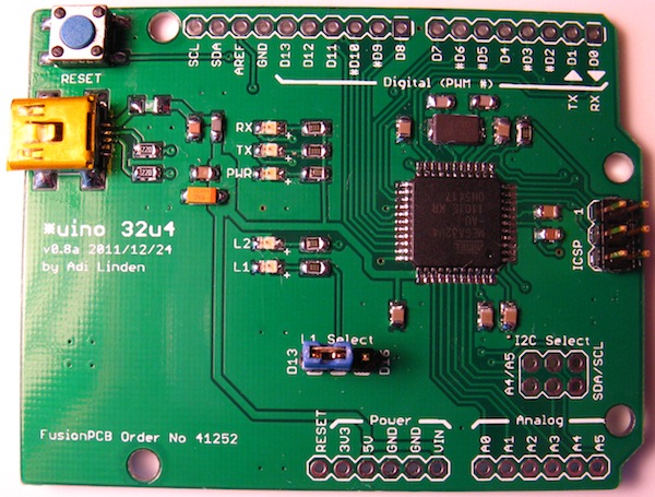
The *uino-32u4 went together flawless. For initial testing I used the Arduino Leonardo bootloader and core files. Since my pinout differs from the Arduino Leonardo this required some translating of digital pins to get the lights to blink. But blink they do. I am so glad to see this actually working. Loading the Leonardo bootloader onto the board using the Arduino 1.0 IDE was trivial and worked without a flaw.
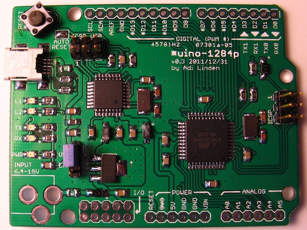
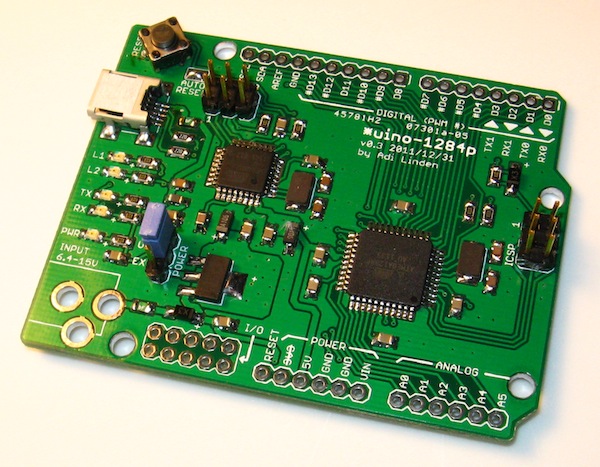
The *uino-1284p went together with minor issues. On the hardware side I noticed that the polarity of the reverse polarity protection diode is marked wrong. To be exact, the schematic is correct, the schematic symbol is in the proper orientation. However, I did add a little “plus” sign to the circuit board to where the anode should be. I erroneously placed the little “plus” by the cathode. When it tried to place the reset tact switch on the board it would not fit. I don’t know if there is a “standard” tact switch, but i picked a different footprint for the switch on the *uino-1284p. I had to make something work by shoehorning a through hole switch into submission. It works and I will have to see what Digi-Key part is appropriate for this purpose.
I was a little concerned about loading the firmware onto the ATmega8U2. It isn’t done via the Arduino IDE and I have yet to find a standalone method to use the AVR ISP MKII on the Mac. Fortunately the Arduino IDE includes everything needed to program with the AVR ISP MKII. While the avrdude executable is not in the default path, it is easily accessed by specifying the full path. Also, the avrdude command line required to get the ATmega8U4 code loaded is well documented in the Arduino distribution. This is the command line I used:
cd /Applications/Arduino 1.0.app/Contents/Resources/Java/hardware/arduino/firmwares
../../tools/avr/bin/avrdude -C ../../tools/avr/etc/avrdude.conf     -p at90usb82 -F -P usb -c avrispmkii -U flash:w:UNO-dfu_and_usbserial_combined.hex     -U lfuse:w:0xFF:m -U hfuse:w:0xD9:m -U efuse:w:0xF4:m -U lock:w:0x0F:m
I used the Mighty 1284P Platform Files to load the bootloader onto the ATmega1284P chip and to build the blinky sketch. I also had to translate from the Mighty 1284P pinout to the *uino-1284p pinout in order to get lights to blink. But all went flawless and now I have blinky lights.
What’s next? * Create pins_arduino.h for each board to reflect the proper pinout * Create the hardware support files and documentation for each board * Create a shield to put each board through its paces to verify digital I/O, analog inputs and PWM outputs.
If you have some spare ATmega8U2, ATmega1284P, or ATmega32U4 itching to be put to use, and are willing to experiment with an unproven board, I am now comfortable making blank boards available.