IRLP Now


… is about the VA3SLT amateur radio repeater in Sioux Lookout. This provides access to IRLP, Echolink and APRS for Sioux Lookout radio amateurs.
Contents:
- Overview
- Mitrek Conversion
- Mitrek Cooling
- Mitrek Tone Board
- Mitrek Squelch
- Repeater Controller
- Repeater PC
- Duplexer Tuning
- Telephone Interconnect
- Repeater Cabinet
- Final Notes
Overview
This article describes the construction of the VA3SLT repeater. The repeater is full-duplex and operates on 147.315 MHz transmit and 147.915 MHz receive. A tone of 127.3 Hz is required to access the repeater.
This repeater provides access to IRLP, Echolink and APRS for the Sioux Lookout radio amateurs. The IRLP node ID is 2590 and callers are always welcome. Echolink connectivity is probided via EchoIRLP and the Echolink ID is 162246. The APRS digi and igate are operating on 144.390 MHz, the national APRS frequency.
The VA3SLT repeater is also a gateway for APRS. An APRS I-Gate and digipeater are operating on 144.390 MHz, the national APRS frequency.
Mitrek Conversion
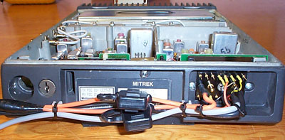
The Motorola Mitrek is the last crystal controlled radio made. It is an excellent performer and well suited for a repeater application. The Mitrek placed into repeater service is a 100W VHF model.
The Repeater Builder website is a great resource of information on modifying commercial radio equipment for duplex repeater operation. Visit the Motorola section of that website for details. These two documents are excellent and a must read for anyone converting a Mitrek to repeater use.
-
Mitrek Model and Chassis Numbers Under: Repeater Builder > Motorola > Mitrek and MSR-2000 Pages (local copy)
-
Interfacing the Mitrek mobile radio to your repeater controller Under: Repeater Builder > Motorola > Mitrek and MSR-2000 Pages (local copy)
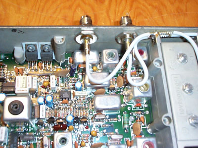
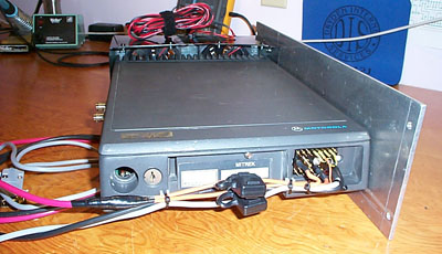
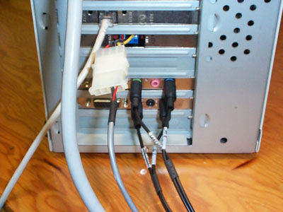
In their original configuration these radios are meant for simplex operation. The radio either receives or transmits but does not do both at the same time. For repeater duty the radio needs to operate full duplex, transmit and receive at the same time. Some circuit changes were required to turn on the receiver all the time, independent of transmitter operation. A pair of TNC bulkhead jacks were installed into the side of the radio chassis. The location was determined by the length of the existing coaxial cables feeding the transmitter and receiver sections. I did not have the proper crimp tool to attach these connectors to the coax. The coax and connectors were both Teflon. Instead of a crimp each connector was soldered by flowing plenty of solder between the crimp ring and the connector body with the coax shield braid sandwiched in between.
New crystals were installed in the channel elements. The receiver was tuned to 147.915MHz and the receiver was tuned to 147.315MHz. No modifications were necessary for the Mitrek to operate at those frequencies. The receiver sensitivity was excellent without any preamplifier. Turning on the transmitter with a full 100 Watt power output did not cause any noticable desense of the receiver.
Mitrek Cooling
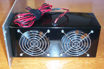
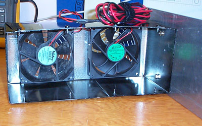
The rated power output of the Mitrek model I converted was 100 Watt. This was by no means a 100% duty cycle rating. While the heatsink of the radio is substantial it is by no means suitable to sink the heat generated when operating on full power. My initial plan of operating the transmitter in the 40 Watt range failed miserably. The PA was apparently not designed to operate at less than about 50 Watt. Current draw of the PA and power output were not in a linear relaionship. It appeared that 65 Watt output was a sweet spot where the output of the PA was clean and current draw was reasonable for my purposes. Heating of the PA was still a problem. A fan cage was constructed that forced air over the heatsink via two 4” fans. These fans turn on when the transmitter is keyed and continue to run for a few minutes after the last transmission.
To evaluate the effectiveness of the cooling I installed temperature probes, one inside the PA compartment and on on the outside of the heatsink. The PA compartment temperature settled at about 65 degrees Celsius after several minutes of continuous keydown and did not rise any further with continuous transmitter operation.
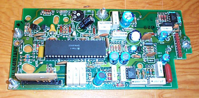
Mitrek Tone Board
There were several HLN4181 tone boards in the batch of Mitrek that I obtained for this repeater project. The Repeater Builder website once again provided valuable information on this particular board.
-
Mitrek HLN4181 PL Board Information Under: Repeater Builder > Motorola > Mitrek and MSR-2000 Pages (local copy)
-
Mitrek HLN4181 reedless PL Board Schematic Under: Repeater Builder > Motorola > Mitrek and MSR-2000 Pages (local copy)
These documents provided sufficient information to build my own elements to try several different CTCSS tones. A 127.3 Hz tone frequency was a good compromise. Higher frequencies produced an audible hum from my HT and mobile radios whereas a lower frequencies where much less responsive.
Mitrek Squelch
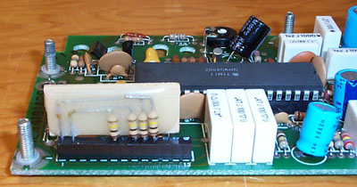
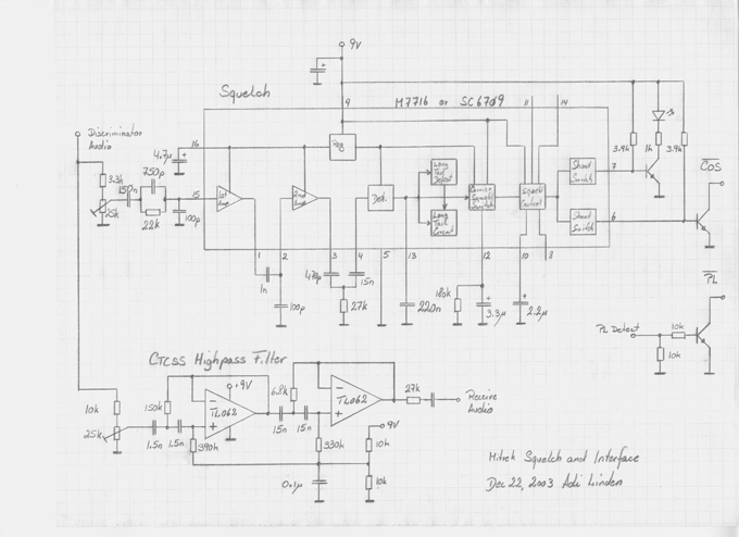
Probably the weakest point of the Mitrek radios is the squelch circuit. The Mitrek was obviously designed for tone operation. The RF squelch performed very poorly with weaker signals. The Motorola Micor on the other hand has an excellent squelch ciruit. Unfortunately the Micor squelch uses a proprietary chip which is no longer manufactured. After purchasing a Micor squelch board on eBay I went to work and integrated the circuit into the repeater controller. I made use of the IC from the squelch board and tossed the remains. Circuit information on the squelch board and the IC came from a familiar source:
- Schematic of the TLN-4310B-2 mobile audio-squelch board Under: Repeater Builder > Motorola > Micor Mobile and Station pages (local copy)
My squelch board was designed to piggyback onto the repeater controller board described next.
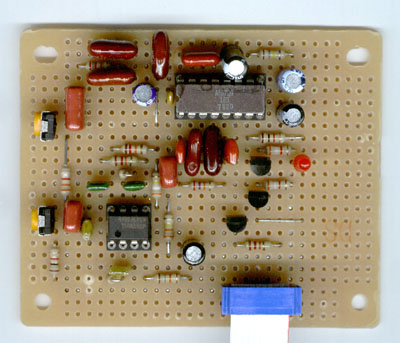
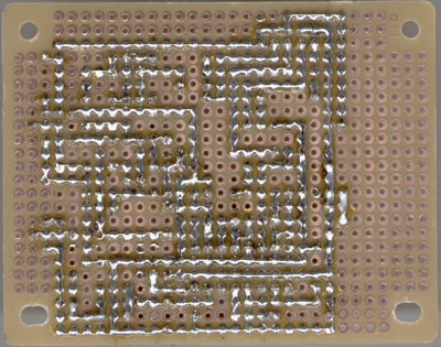
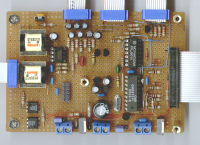
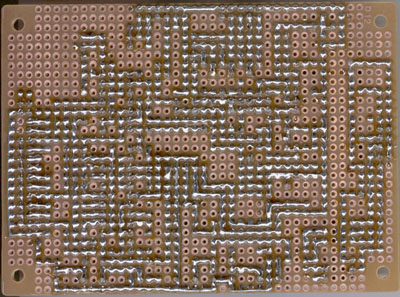
Repeater Controller
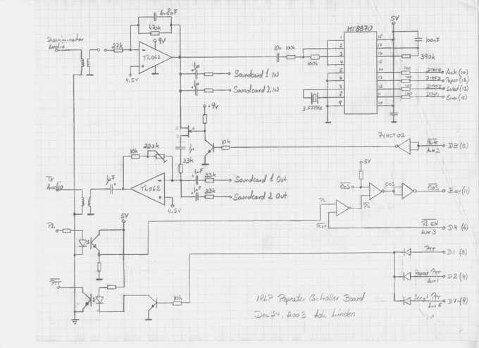
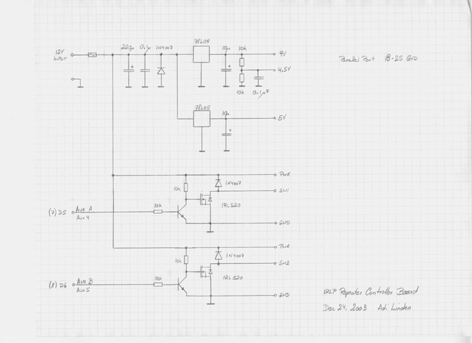
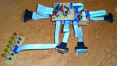
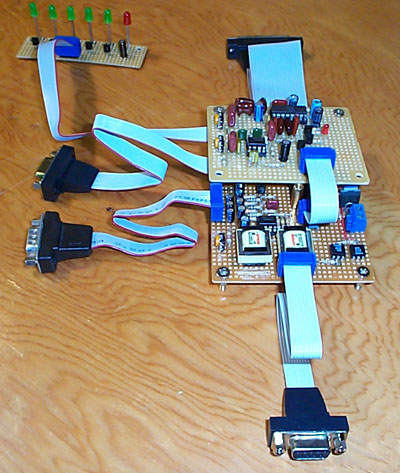
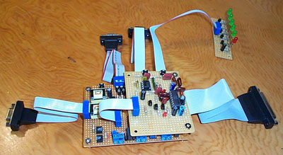
Dave Cameron, the father of ILRP, created some code to control a repeater from a standard PC running Linux. The required hardware consisted of an IRLP controller board and some additional audio circuitry. I decided to design my own hardware incorporating the IRLP hardware, additional IRLP aux ports and the circuity to mix and switch the various audio sources. My previous IRLP setups showed that proper isolation between the PC and the radio hardware was a absolute requirement. The controller hardware included audio transformers and opto couplers to keep radio ground and computer ground seperate.
The schematics to the left document the original design. This does not include some of the design changes incorporated later in the development process. Noteworthy changes include the addition of telephone interconnect audio ports and modifications to the DTMF decoding section. I have yet to produce new clean drawings with the latest changes incorporated.
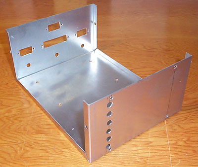
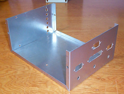
The controller hardware was installed in a aluminum enclosure to provide RF shielding. A small board with status LEDs was designed and mounted in the front of the box. The whole assembly was attached to a rack panel for mounting in the repeater cabinet. There was plenty of unused space on the rack panel. A small speaker and amplifier were installed to allow local monitoring of repeater activity.
Repeater PC
The processing intelligence of this repeater is the PC running Linux. It connects to the repeater hardware to interface to the local radio equipment and connects to the Internet to access the IRL and Echolink networks. Repeater controller software running on the PC takes care of “normal” repeater operation for local use of the repeater. The IRLP software runs in parallel to repeater controller software.
In good Open Source spirit I have taken the code that Dave Cameron released and built upon it. There have been many enhancements and tweaks. The system has been rocksolid ever since it went “on the air”. All the feature one would expect to find in a repeater controller are supported:
- Basic COS and CTCSS controlled repeater operation
- Interoperability with IRLP
- Configurable courtesy beeps for different repeater states
- Intelligent CW repeater ID
- Fan control
The code I produced remains open source and is available here. This code still lacks considerable documentation and proper acknowledgment of its origin and contributors.
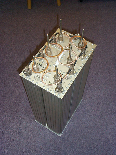
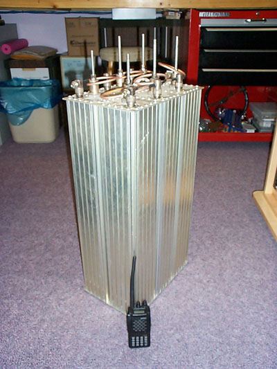
Duplexer Tuning
One of the big learning experiences of this project was tuning the duplexer. There were many challenges and interesting observations. Perhaps the most significant point to note is that the Mitrek solid state PA does not have a constant consistent impedance. Different power levels affected the impedance of the PA. This made cable lenghts between transmitter and duplexer critical. A great piece of equipment to solve the impedance mismatch between PA and duplexer is an impedance matcher (or “Z-Matcher”). I purchased the 6450/Z Impedance Matcher from EMR Corporation. The impadance matcher is located as close as possible to the transmitter output and tuned to match the PA output to duplexer input.
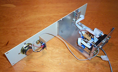
Telephone Interconnect
The telephone interconnect is an old surplus Connect Systems Incorporated (CSI) device. No major electrical modifications were need. The original front panel was removed and the chassis was mounted on a custom blank rack panel. A Cisco ATA186 device is connected to provide dial tone via my home Asterisk PBX.
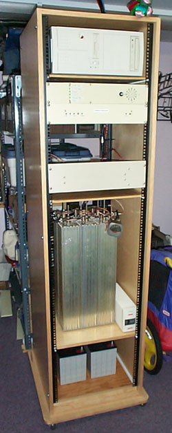
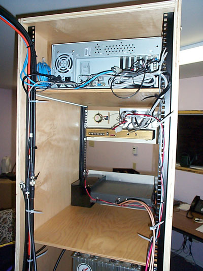
Repeater Cabinet
There is nothing quite like fine birch plywood furniture. The repeater cabinet is constructed from veneer birch plywood. The finishing consists of multiple coats of water based Varathane polyurethane finish. Front and rear rack rails provide mounting locations for the various pieces of repeater equipment.
Final Notes
This completes the construction article of the VA3SLT repeater. On the outside the repeater feed into a GP-9 omni-directional antenna mounted at the top of my tower. Even though the GP-9 is a multi-band antenna it is dedicated the VHF repeater duty. The feed line is LMR-400. Although many dispute the qualities of LMR-400 it has performed well so far. Apparently it is possible that physical movement do to wind or temperature changes cause noise as the braid shielding rubs against the aluminum shielding. I have had no indications of any problems so far. Another caveat of LMR-400 is the center conductor. The center is aluminum with copper coating. It is important that the copper coating is not damaged at all during connector installation. Even a nick in the copper will increase the resistance and weaken the center conductor. In combination with a high power transmitter this will lead to failure of the cable.
This project wouldn’t have been possible without the Amateur Radio Society of Dryden who provided the duplexer and antenna.