Interfacing the Motorola Mitrek mobile radio
to a repeater controller - Ver 2

By
 

Comments and additional material are welcome
(even "Hey - you've got a typo at..." messages...

Note: If you decide to print this file to put in your Mitrek manual make sure that the circuit diagrams below show up in a monospaced font (like Courier) if you want to see them properly.   I used an exclamation point as a vertical line since the actual vertical line character (upper-case backslash on many keyboards) is one of the first ones replaced by a local language character in non-USA keyboards and as a rule I make my writeups as international-compatible as possible.

This writeup discusses how to modify any common Motorola Mitrek mobile two-way radio to add connections for a repeater controller.   These modifications are frequency independent - all they affect are audio and controls (push-to-talk, etc) and were originally developed for a dual UHF radio configuration (one for receive, the other for transmit) that implemented one end of a full duplex point-to-point link, but will work on any regular single Mitrek radio, a duplexed Mitrek, a tabletop base (Motorola calls it a "Super Consolette"), a tabletop base converted into a repeater or dual Mitrek configuration, even in mobile extender usage.

I started this mod writeup as a set of handwritten notes on ruled paper in the back of my Mitrek binder as I read through the Mitrek manual.   Then I got my hands on some surplus Mitreks, and Googled every mention of "Mitrek" and "modify" or "modification" or "repeater" or "remote base" on the internet and printed the articles.   Then I reverse engineered every mod to see what it did, and on some I tried them out - for example audio mods were tested using a HP-200CD generator swept from 100hz to 5khz and a Heathkit distortion analyzer.   This writeup is the result of my experiments and experiences.

All of this work was done in a negative ground environment.   The Mitrek mobile radio itself can be cabled for either positive or negative ground, but if you are using this info to help you build a mobile extender in a positve ground environment please realize that you are plowing a new field and are on your own.   In all my years of working on commercial two-way radios I can count the number of positive ground installations I've been involved with on one hand and have multiple fingers left over.

The reason I used Mitreks in my system was that the Mitrek is an excellent performer, readily available, inexpensive (because everybody wants synthesized radios like Maxtracs where the Mitrek uses crystals - in fact it was the last crystal controlled mobile that Motorola made), and it is easy to work on (it uses pin and hole components instead of surface mount).

I used dual radios since you can't duplex 406-420mhz Mitreks and keep them clean, so my initial implementation used two 450 Mitreks tuned to the regular user input and output frequencies of the far-end repeater (443 and 448mhz), later replaced by 420mhz Mitreks on real link frequencies.

This is a "cafeteria collection" of modifications - no one mod is dependent on any other mod - you can pick and chose which ones you want to implement.   If you are going to use two radios to implement a repeater or a duplex link, I suggest you make the mods to both radios leaving half of each radio idle so that if something dies and you are in a pinch you can simply swap the radios and be back on the air, then at your leisure swap out the half dead radio with a good spare.   Note that this means that to implement your first one-way point-to-point link you need to buy at least four radios... one for TX at site #1, one for RX at site #2, one for a shelf spare, and one to blow up while getting familiar with the Mitrek (and then to use for spare parts to keep the other three running).   You can also make the same four radios a duplex link, as long as they aren't 406-420 radios.   If you are implementing your first Mitrek-based 420mhz full duplex link you will need six... (a pair at the near end, a pair at the far end, a shelf spare and the sacrificial lamb...).

There is some deliberate repetition in this text - please excuse that as you read it, but since I wrote this document as a cafeteria collection a few things need to be mentioned in each relevant section.   Even with this separation into individual mods I recommend that you read this entire document all the way through at least once before you heat up the soldering iron.

Make sure that you have a correctly working radio, on the frequency of interest before you start the mods.   You don't want to start modifying a radio, and when it's done dicover it's not working, and you don't know if it's the radio or the mods that are messed up.

I guarantee that you will also find typos, and at no extra charge.   A lot of these 43 pages were done late at night after everyone else had gone to bed.   I don't mind emails pointing them out, either.   And to update one of my dad's old jokes, the new PC keyboard can't spell any better than the old one (he was 6AAU at age 14, let it lapse when he moved to Toronto, then relicensed in the late 1970s as WB6SOX... was an old time newspaperman and a professional photographer... the original joke referred to when he upgraded his office from an Underwood mechanical typewriter to a Smith-Corona portable typewriter in about 1967-1968 and then to a dual-pitch IBM Selectric in 1981 or so).

The modifications described in this document are generic and nothing in the repeater controller needs to be adapted to the radio, with one exception: if you plan on using the the stock Mitrek carrier squelch to drive the COR / COS / carrier detect line (the signal to the controller) then the controller has to be able to mute the receiver audio which some of the ACC controllers couldn't do (they relied on the receiver audio muting).   There was a mod for the ACC that used the fact that driving the reset line of the audio delay board chip with the COR signal would mute the audio, but that wasn't well documented or distributed.   If you use the Link-Comm RLC-MOT board to add a Micor squelch to the radio then even this concern is eliminated.

The dual radio setup described here has been personally tested by me on three different controllers, one was home-brew Z80-based, the second was a home-brew PIC processor, and the third was an Scom 7K.   Emails have reported that this information has been used on several single simplex and duplexed mobiles (used as remote bases), several more dual radio combinations (used as point-to-point links), and at least two full duplex tabletop base stations, and with controllers by Creative Control, Computer Automation ("CAT"), Link (RLC-series), Pacific Research and NHRC, so I am confident that there are no hidden problems in this procedure.

Note that everyone who plans on using a UHF Mitrek in repeater or link service should read (and then re-read) the excellent Cactus Radio writeup on these radios located at http:// www.cactus-intertie.org/LA/tec_not5.pdf.

I keep my Mitrek manuals in a large 3-ring binder and also included are doc sheets on my mods plus printouts of various Mitrek related web pages.   You should print the Cactus Radio writeup, read it, 3-hole punch it, and put it in >>your<< Mitrek book - it is a very well done writeup and is full of excellent technical info.   There is one conflict between Cactus's writeup and this one, they bring repeat audio out on the connector pin that I use for the PL decode logic level, but please read both sets of info and make your own choice on signal routing.   I especially call your attention to page 4 of the Cactus writeup concerning the transmitter tuneup precedure and capacitor C-800L (that's C-eight hundred-L).   I lost two UHF transmitters before I discovered that quirk...

If you have already read through this and are returning to reference a certain section you can jump ahead to any section using these jump links:

These mods were developed using a pair of T34JJA 30w UHF Mitrek radios as test beds.   The radios started out life as mobiles on a 464mhz and 469mhz commercial community repeater frequency pair (chassis numbers HUE1074C and HUE1082C).   For a model and chassis number lookup list see the web page at http://www.repeater-builder.com/mitrek/mitrekmodnum.html.   If you have a Mitrek chasssis number that is not listed there please send me full information so I can add it.   Please don't email me asking about any chassis number not listed - all the info I have is already up on the web page.   Note that many of the Mitrek chassis are very similar - for example, the same high power chassis can have any of 8 different chassis numbers depending on if the receiver preamp was factory installed or not, and if the output power control variable resistor was set to 60, 75, 90 or 100 watts.

I have low band, UHF and consolette manuals, and before web-ifying this writeup I compared them to a friend's high band manual, mainly to make sure the component designators for the resistors, capacitors, jumpers, etcetera that I mention here did not change between manuals.   Since these mods only affect the audio and squelch circuits they should transfer over with no problems, but they have not been tried on actual low band or high band hardware (yet)   (June 2003 update: I have since received emails from four different folks that have converted low band and high band radios using this information and they state that everything matches).   And there is now a highband manual in the file cabinet.

Get the manual! This document is complete as I can make it as far as how to connect a Mitrek to a repeater controller, but is not a substitute for a real manual - and you will need one anyway to tune up the radio.   You can call Motorola Parts at 800-422-4210 and they will be happy to take your credit card or ATM card info and ship you a manual.   You can also watch ebay and the other auction web sites for Mitrek manuals... Click here for an ebay search on "Mitrek".   New manuals from Motorola are about US$30 each and the part numbers are:   (note the trailing letter chassis version...)

The Mitrek "Super Consolette" tabletop base radio has it's own supplement manual: 68-81040E80.   You don't need this manual to do any of the mods listed here, but if you end up with a tabletop Mitrek base it's very, very nice to have, especially if your unit has any options like DC (or AC) wireline remote control, VU meter, battery back up or channel scan (yes, Moto offered a scanning base station).   Note that you need the appropriate mobile manual (low band, high band, UHF, 800mhz) to go along with it as the Mitrek tabletop base is simply a pretty box that contains the power supply, the volume and squelch controls, the frequency switch, a speaker, a 1:1 audio transformer (between the Mitrek chassis and the speaker) and a mobile radio chassis.   And if you end up with the high power (i.e. the larger) power supply then you can run a low power tabletop repeater.   The chassis even has a hole for a second antenna jack pre-punched (then hidden behind a label).

As long as your are ordering manuals, you will want to order the Mitrek tuning tool set, part number 66-82977K01 (unless you have a huge collection of diddle sticks - I have the standard 20-year collection that fills a wooden cigar box.... even a piano tuner's wand for doing the old solenoid-tuned wide-spaced UHF Motracs).   The real Mitrek tool is only $2.92 (as of May 2004) and breaking a slug with the wrong tool is not worth it.

The Mitrek Plus supplement is 68-81046E05 and is definitely worth getting if you can get one...   the last time I called they were out of them and not planning to reprint them.

For more information on manuals and how to order them, see the "How to order manuals or parts from Motorola" web page that can be reached from the main Motorola page.   The "Figuring out what you have" page can also be useful.

Another note... the UHF book that I have (68-81045E75-A) is the only Mitrek manual I have in my collection that has documentation on all three PL and DPL boards - the HLN-4020 reed-type PL board, the HLN-4181 "reedless" (also known as the "tone-element") PL board and the HLN-4011 DPL board.   And the late UHF book - the 68-81045E75-B does not have the HLN-4181 board in it!

The -A revision highband book I looked at does not have a HLN-4020 reed-type board schematic.   There may be a newer rev out there.

The -O original low-band book I have does not have the HLN4181 reedless PL board or the DPL board documentation.   There may be a newer rev out there.

Note also that the Mitrek is an all-metric radio - don't casually mix the leftover screws into your parts bin.


Now I'm going to define some terms that I'll use in the rest of this writeup:

Lastly, be aware that the same jumper number can appear in multiple places - there can be a JU3, for example, on the main board, another JU3 on the interconnect board, a third JU3 on the PL board and maybe a fourth JU3 in the control head.   I've made a point of specifying where a specific jumper is when I mention it, but keep this in mind, especially if you are reading someone elses writeup.


Since a repeater or a point-to-point link is a single frequency beast the four frequency select leads plus the "SP" (spare) lead in the cable (pin 18 - the middle big pin) are available for reuse as input and output pins.   Note that there is a 0.01uf capacitor between the F1 lead (pin 7) and ground (at C602).   If you are going to reuse that pin, you might want to remove C602, depending in how you use it.   If yes, it's right next to the Frequency #1 transmit channel element.

There are two versions of the Mitrek: the early "Mitrek" and the later "Mitrek Plus", however you can't tell which one you have without looking at the radio's interior or looking at the chassis number.   The differences are fully documented in the Mitrek Plus supplement manual I mentioned above and among other things the "Plus" radios have extra IF filtering and some filtering chokes on the control cable pins.   The Mitrek Plus really is the preferred radio when you go hunting for Mitreks.   Not that the regular Mitrek isn't a fine radio, just if you have the opportunity to paw through a pile of radios it makes no sense not to pick the better ones...

To determine which version you have you will have to do one of the following:

  1. Look at the chassis number (the Mitrek Chassis and Model Numbers web page lists all the ones that I know of)


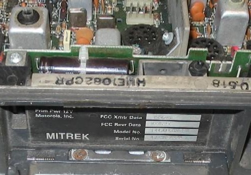
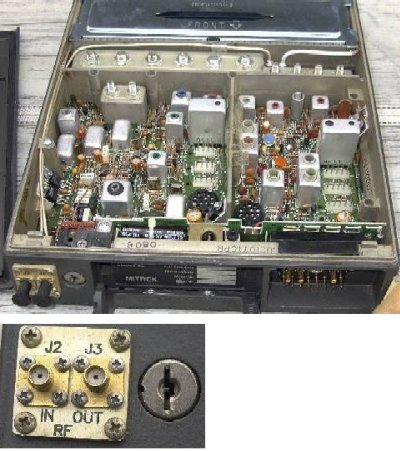
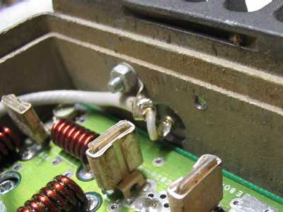
    Photo 1: In this photo you can see the HUE1082CPR chassis number stamped on the chassis lip.   On this particular radio the "U" looks strange in the photo because it has a screwdriver scratch through it.

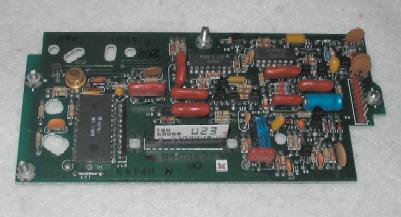
  2. Look for Y204 - the extra receiver IF crystal filter:

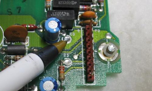
    Photo 2: This is a Mitrek - the pen points to the jumper that replaces the filter (this is a carrier squelch radio - no PL board - note the red connector at the bottom left - this is where the PL board plugs in.)

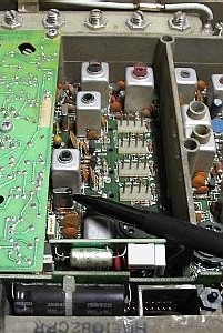
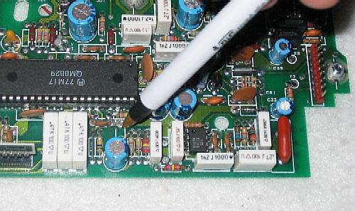
    Photo 3: This is a Mitrek Plus - the black pen points to the extra filter - (yes, this radio has a HLN 4020 dual reed PL board in it).   If you need to add Y204 to a radio it's Moto part number 48-84396K02.

  3. Look the back side of the interconnect board around the back of control connector for several RF chokes.   In a number of places where the interconnect board silk screen has JU (for jumper) the Mitrek has a wire jumper and the Mitrek Plus has a choke - but not always.   The later interconnect boards had the "L" designation in the silk-screened labeling, the earlier boards had the "JU".   There were Mitrek Pluses made with L-designations and jumpers in place.   Finding a radio with chokes is nice, but a later board (with L-designations) is better (chokes are easy to make and can be added).

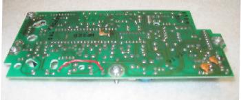
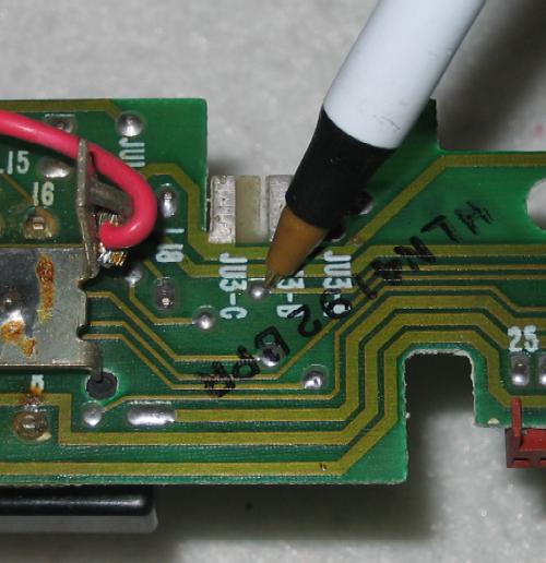
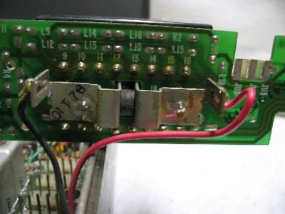
    Photo 4: This is the back side of a later interconnect board. Note the "L" markings in white ink at the top.   Early boards had "JU" markings.
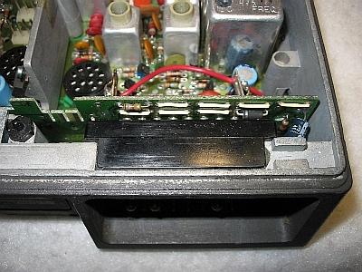
    Photo 5: This is the front side of the same interconnect board - but it has jumpers (the wires with white sleeving) in place of the chokes.
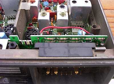
    Photo 5A: This is the front side of a later interconnect board - when Moto switched to automated assembly the hand-installed wire jumpers were replaced with zero ohm resistors which could be inserted by the automated component insertion machines.   These jumper replacements can be identified by a single black band in the middle of the resistor body.

  4. Another artifact to look for the two large tubular electrolytic capacitors on the left side of the interconnect board - the book says that they are 500uf in the Mitrek, and are 1,000uf in the Mitrek Plus - but I have found 1,000uf capacitors in the radios that don't have Y204... almost if the parts list used to stuff the interconnect boards during manufacture was updated and a large number of boards produced before Y204 was added to the main board.   Note that you may have to remove the interconnect board from the radio to verify the value of the capacitors.   If you can't, note the body length and lead bending angle.   But realize that the larger caps only indicate a later production run of the interconnect board and in our use (repeater or link service) are totally irrelevant (they only affect the speaker audio).

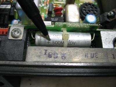
    Photo 6: This is the interconnect board in a Mitrek - the pen points to the upper 500uf capacitor (there are two identical caps, one above the other)
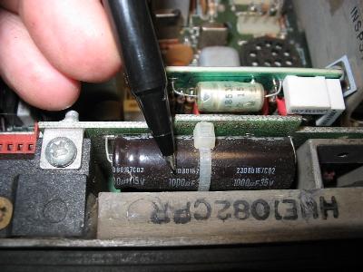
    Photo 7: The capacitors in a Mitrek Plus are 1000uf

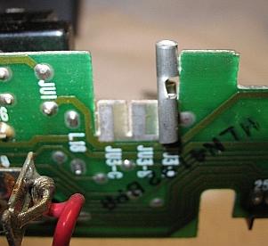
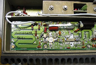
  5. This is the most important item in link or repater duty - look for the RCA connectors.   Trace the two coaxes from the antenna relay.   One of them will go to the middle of the tuned lines right in front of the PA deck.   The early radios had the coax wired into the front end, the later ones had RCA plugs.   You want the ones with the plugs.

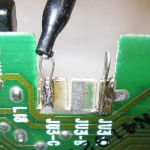
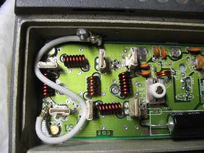
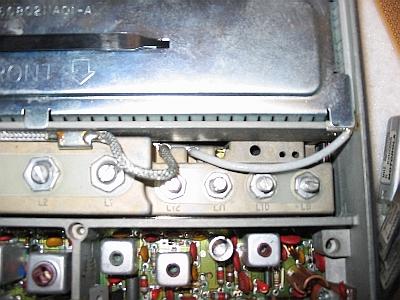
    Photo 8: The silver braid cable on the left in this picture comes from the antenna relay and connects to the RX front end - note that it is wired in to the tuned circuit casting.   The white teflon cable on the right couples the exciter output to the PA deck.
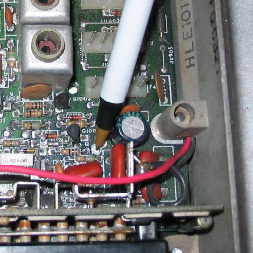
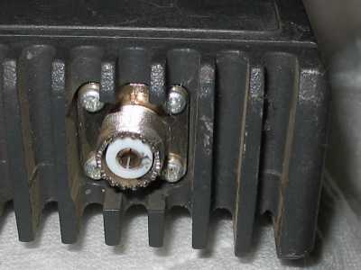
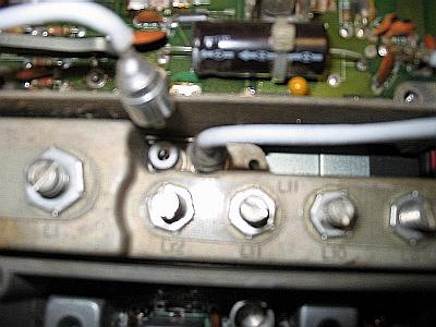
    Photo 9: In a Mitrek Plus the same coax has RCA plugs.   The big screw on the left ("L1") is the first RX RF helical, the 4 screws on the right ("L12", "L11", "L10" and "L9") are the exciter filter.

The Bottom Line:   If you have a choice when you select a radio, pick a Plus radio by the chassis numbers that are on the Mitrek Chassis and Model Numbers web page, but if you don't have that list with you (I have it in my Palm Pilot) by all means pick the radios first with the the RCA connectors on the front end / exciter filter assembly. The second item to look for is the Y204 extra IF crystal filter - but if it's not there is can be added easily.   Third, try and get at least one set of channel elements per radio - and really try and get the original elements with the radio - and then test it using a dummy load and a sig generator before you make any modifications.   You don't want to convert a radio then find out it's dead, and you can't tell if the problem is in the original radio or the conversion.   If you can't get the original elements, then get ones that you can recrystal to your needs.   Make sure that the elements you do get are the proper ones... one of my 6 meter radios came with UHF elements in it - and the seller obviously knew they were the wrong ones because he had carefully removed the model number / frequency stickers from the elements).

Mitrek Channel Elements
  Receive Transmit
Low band (0.0005%) KXN1085 KXN1087
High band and UHF (0.0005%) KXN1086 KXN1088
High band and UHF (0.0002%)
These are designed for the MSR-2000 repeater but will work just fine in the Mitrek mobile.
KXN1112 KXN1095
The second receiver of a 2-receiver MSR-2000 base station or repeater uses a 10.8mhz IF and uses a KXN1086BA element.   This is a normal element internally, the "BA" part number just clues the rock-chippers to offset the local oscillator frequency by 100khz to compensate for the shifted receiver IF frequency (the primary RX uses a normal 10.7mhz IF).

If you are picking radios and heads out of a pile to build a repeater or a single frequency link pick a single-frequency head with the monitor switch and be sure to pick out a multifrequency cable.   Moto supplied two cables with the Mitrek, one without pins 6, 8, 9 and 10 and the other with them.   Look for white, grey, blue and black wires (labeled on the control head end with the numbers).   Also make sure that you have a pin 18 - it is a black-grey wire.

Mitrek front panel with missing handle

Photo 10: The front panel of a Mitrek mobile.   Visible is the antenna connector, the mounting tray lock, the model/serial number tag and the control connector.   Above the number tag is the spring-loaded top cover release, it looks like a nut driver would be used to turn it, but in reality it's a pushbutton.   The key is the standard Moto mobile key - a Chicago Lock and Key H2135.   For more info on two-way radio keys visit the keys page.   On the particular radio shown in the photo the fold-down handle is missing.
Foam rubber gasket
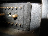
Photo 11: Don't be surprised if some radios have a foam gasket on the control connector.

By the way, you will want to print the jumper table below and stuff it into your Mitrek manual as I've never seen anything listing the interconnect board jumpers in ANY of the Mitrek manuals I've seen, even on Moto's schematic of the interconnect board (the ones I have show no jumpers or chokes, just direct connections).   I put this list of jumpers together as I traced out the interconnect board as I modified my link radios.

Mitrek Control Cable Pinout
The view below from front of the radio or back (wire side) of control cable plug.
   +-----------------------------------------+
   !                                         !
   !  16   15   14   13   12   11   10    9  ! -------------
   !                                         ! The cabling (to the vehicle
   !     19        18       (T)       17     ! battery and the control cable
   !                                         ! to the head) comes out this side
   !   8    7    6    5    4    3    2    1  ! -------------
   !                                         !
   +-----------------------------------------+
The "(T)" in the drawing above represents the large thumbscrew that mounts the control cable connector into the radio.
Control
connector
pin
Cable
lead
color
Early
Interconnect
Board
Jumper
Later
Interconnect
Board
Jumper or
Inductor
     Pin function in radio
1 Brn JU5 L1 Mic hot
2 Shield     Mic gnd
3 Orange X (trace cut) Speaker (floating !)
4 Yellow     Switched and fused +12 from control head (RX power)
5 Green X (trace cut) Speaker (floating !)
6 Blue     Frequency select switch wiper
If operating with out a control head connect this pin to pin 17.
7 Violet JU6 L7 Frequency 1 select
used for PL encoder control in this collection of mods
8 Grey JU7 L8 Frequency 3 select
used for COR / COS (carrier sense) to the repeater controller
9 White JU8 L9 Frequency 2 select
used for repeat audio out (audio out - from the RX to the repeater controller)
10 Blk JU9 L10 Frequency 4 select
used for repeat audio in (audio in - to the TX from the repeater controller)
11 Blk/Brn JU10 L11 Audio to control head Vol / Sq pots
12 Blk/Red     Jumper this pin to pin 4 (TX enable)
13 Blk/Orn JU11 L13 PTT in (gnd to TX)
14 Blk/Yel JU12 L14 Sq pot wiper
15 Blk/Grn JU13 L15 Vol pot wiper
16 Blk/Blu JU14 L16 Ground to put RX into PL mode - normally hooked to control head and then to the microphone hang-up box.   In our use this wire will not be connected.
17 Big Black JU1 JU1 (big pin) Ground - DO NOT CUT JU1
18 Blk/Gry JU15 L18 (big pin) connects through JU15 and then to one side of both JU3A and JU3B on the interconnect board.   Used here for PL decoder logic level output (PL sense) to the repeater controller
19 Big Red JU16 L19 (big pin) +12v (supplies power to the PA deck directly, and via JU16 / L19 to the rest of the radio)
Note: "X" in the jumper column above signifies that there is an unlabeled jumper on the early interconnect boards - if you want to use it you'll have to trace it to find it.   The later boards (with silk-screened "L" designators) have traces that can be cut to accomplish the same functionality.

If you are going to use a Mitrek that does not have the chokes on the interconnect board in a repeater system consider replacing the jumpers with chokes in the leads that you use as interface connections to the outside world.   Just take common carbon resistors and use them as coil forms, wrap them in 22,24 or 26 gauge enameled wire and solder the wire end to the resistor lead close to the resistor body.   Stretching the wire slightly before you wind it helps it lie flat, and a drop of varnish, hot-melt glue, or even clear fingernail polish on the starting end helps hold it in place while you wind the rest of the coil, then another drop on the tail end holds it in place while you solder the end.   Some clear heat-shrink tubing will finish the job.   As long as the resistor value is over 40-50 ohms the actual value doesn't matter as the choke will short it out.   A free source of enameled wire is the deflection yoke or the high voltage transformer from a old TV set.   Stretch it by clamping one end in a bench vise (or a fence post) and string off 6 to 10 feet and lean back with your whole body weight.   Then wind the choke with the stretched wire.

If you decide to improve the RF filtering of a radio and you intend to do all of the mods listed here you will need to replace the jumpers with chokes at pin 7, 8, 9, 10, and 18.   If you want to go overboard you can also add one more choke on pin 1 (which handles local microphone audio).   The simplest way to add them is to cut the jumper on the connector side of the board, melt the solder and remove the two wire ends, suck the remaining solder out, and install the choke into the same holes but on the the side of the board facing inside the radio.   Note that three of the jumpers (at JU6/L7, JU7/L8 and JU16/L19) are buried under a large coupling capacitor - you will need to lift one end of the cap to remove the jumpers.

As long as you are inside the radio lift off the PA deck cover and do a visual check the tantalum electrolytic bypass capacitors on the positive 13.8 volt supply rails - and use a good magnifying glass.   Replace any that look suspicious.   The failure mode is that they go down in value or open up, and either can allow spurs...   A second problem is that some radios didn't have enough driver stage bypassing.   If you still have spurs (rare) add a large value cap on the driver stage +12v lead.   Another Mitrek failure mode is intermittent connections in the preselectors, and the Cactus writeup mentioned above has the cure for it, as well as WB4HFN's web page... see http://www.wb4hfn.com/Modifications/MT2311.


In a normal mobile installation pin 19 is hooked to the positive side of the vehicle battery through a big fuse.   Constant and ignition switched power is run to the control head via relatively small wires (#20).   In a normal mobile installation the RX can be run with the ignition key off, and the key must be on for the TX to be enabled.

Normal mobile installation:
                                                                         Control connector
                                     thick wire                          on radio
Pos --- Big Fuse ------------------------------------------------------- Pin 19
12v     Amperage depends                                                 (PA deck) 
        on the TX power 
        level of the radio.

                                     thick wire
Gnd -------------------------------------------------------------------- Pin 17


                                     thin wire          control head
           Gnd ---------------------------------------- Pin 17
     (under dashboard)

                                       inside the control head
                                       !---------------------!
                                       !                     !
                                                   /
constant +12 from                   control       /         control      control 
underdash fuse box                  head         /!         head         connector
(e.g. the battery  ---- 7A fuse ----pin 19 -----O !  O------Pin 4 -------Pin 4
side of the clock                                 !                      (RX power)
fuse)                                             !
                                                  !/
switched +12 from                   control       /         control      control 
underdash fuse box                  head         /          head         connector
(e.g. the battery  ---- 7A fuse ----pin 20 -----O    O------Pin 12 ------Pin 12
side of the broadcast                        double pole                 (TX enable)
radio fuse)                                  power switch
                                        (part of the control 
                                         head volume control)

If you are not going to use a control head (for example, mounting the radio on a rack panel, with the controls mounted to the rack panel or in in the lid of the radio), or if you want very simple wiring, we can consolidate and simplify the power wiring as per the schematic below (using the power switch on the power supply as the on/off switch):

                        thick wire       Control connector
Pos --+-- Big Fuse ----------------------Pin 19 (PA deck + TX) 
12v   !
      !
      +-- 7A fuse --------------------+--Pin 4 (RX power)
                        thin wire     !
                                      +--Pin 12 (TX enable)


                                      +--Pin 6 (frequency select logic)
     thick power wire    thin wire--> !
Gnd ----------------------------------+--Pin 17 (radio ground)

The size (amperage) of the big fuse depends on the band and power 
level of the radio.

Some folk run the hot side of the 7a fuse to pin 19...   I don't like to do that because if the big fuse blows for some reason it will kill the RX as well.   You can run the 7a fuse either to the positive 12v directly or through the big fuse, whatever works easier for you.   In my case I was dedicating an Astron power supply to the dual link radio assembly plus I was using a control head so I added a large in-line fuseholder for the transmit pin 19 plus a small fuseholder for everything else.   I put both of them in the cable harness that coupled both radios to the control head and the power supply.   A diagram of the power wiring is later on in this writeup.

If you are not using a control head you can connect your own speaker, volume and squelch controls as follows (don't forget to ground the Frequency 1 channel element pin - read further on for notes on JU611):

         interconnect board    ! control !
         and control connector ! cable   ! control head
       !-----------------------!---------+----------------+
       !                       !         !                !
        +!!C1                 
radio ---!!----------Pin 3 ----------------pin 3---Pin 29----
main     !!                                (in)      or       \ 
board                          !         !         Pin 31    speaker - note that
                               !         !          (out)    both sides are hot!
        +!!C2                                                 /
radio ---!!----------Pin 5 ----------------Pin 5---Pin 32----  
main     !!                                 (in)    (out)
board                          !         !
                                          
radio---------JU13---Pin 15 ---!-----------Pin 15-------------------+
main          L15    Volume                on head                  !
board                wiper     !         !                          !
                               !         !                          !
        +!!C3                                                       !
radio----!!---JU10---Pin 11 ---------------Pin 11---+-----+         !
main     !!   L11    Buffered              on head  !     !         !
board                audio out !         !          !     !         !
                               !         !          \     \         !
                               !         !    3.3k  /     / 10k     !
                               !         !    1/4w  \     \ 1/4w    !
                               !         !          /     /         !
                               !         !          !     !         !
                               !         !          !     !         !
                               !         !          !     !         !
                               !         ! 25k pot  \     \ 25k pot !
                               !         ! Squelch  /     / Volume  !
                                                    \     \         !
radio---------JU12---Pin 14 ---!-----------Pin 14-> /     / <-------+
main          L14    Squelch               on head  \     \
board                wiper     !         !          !     !
                                                    !     !
radio----------------Pin 2-----!-----------Pin 21---+-----+------Pin 27--+
main                 Audio                 on head              on head  !
board                ground    !         !                               O  /
                               !         !                    Hangup box   /
                               !         !                    (mic clip)  /
                               !         !               /               O
         1.8k                                           /                !
radio--+--R---JU14---Pin 16 ---!-----------Pin 16------O  O------Pin 24--+
main   !      L16    PL/Carrier            on head  "Monitor"    on head
board  !             Squelch   !         !          switch on
       !             select    !         !         control head
PL     !                       !         !        (PL/CS select)
board--+

The actual Monitor switch in the head is DPDT, and the second pole is used with other options like channel scan, 2-tone decode, or PAC-RT remote extender (mobile repeater).

Capacitors C1, C2 and C3 are located on the interconnect board.   C1 and C2 are 500uf in the Mitrek, 1,000uf in the Mitrek Plus.   C3 is either 4.7uf or 10uf depending on the vintage of the radio.   If you find a 4.7uf cap in your radio as C3 I suggest you change it (or just parallel another one across it) as the higher value improves the RX audio.

The lead for pin 16 is not required in 99% of the amateur applications - most repeater controllers use separate carrier and PL decode lines rather than one line and a carrier squelch / PL select line.   Most radios in amateur radio repeater service usually sit in carrier squelch mode forever, and the repeater controller does all the work in selecting PL or Carrier squelch mode by selecting either the carrier squelch or PL decode line, or ANDing them together.   If you end up needing an extra wire in the control connector you can cut the JU14 / L16 jumper (disabling the carrier / PL switch on the control head) and solder to the pad on the interconnect board that connects to pin 16.   Then tie into pin 16 by the head.

You could mount the volume and squelch pots inside the radio and tie them to the radio side of JU10 / L11, JU12 / L14, JU13 / L15 and to ground, but it's a bit cramped inside.   Doing so, however would free up pins 14 and 15 which could be used for other things, at the possible expense of not being able to bench test the radio with a standard cable and head.   If you are going to mount the volume and squelch controls any distance from the radio remember that Moto uses a braided shield around the conductors connected to pins 11, 14 and 15 on the control cable connector, with the shield hooked to pin 2 on the radio end (audio ground) and pin 21 on the control head end.

The Mitrek volume and squelch pots are 25k ohms which is not a common value in the electronic component world (especially in the surplus world) - the common ones are 10K and 50K.   The Mitrek "clamshell" control head uses PC board mount pots with shafts and knobs, and the "ACM" - short for "Alternate Control Module" - head uses PC board mount thumbwheel pots.   If you are going to mount the controls on a rack panel you need to locate an old Motrac, Motran or Mocom-70 mobile control head to scavenge the regular panel-mount pots from.   DO NOT try to use the earlier radio's head directly on the Mitrek without modification as the older radios used a speaker connection that had one side grounded, where the Mitrek uses both sides of the speaker hot (the mod is a simple one).   If your old head came with the palm microphone you can scavenge it and the mic jack and use it on the rack panel as well.


In the rest of this writeup I am going to assume that you are either modifying a Mitrek Plus radio (with the factory inductors on the interconnect board) or you have replaced the above mentioned JU6 / L7, JU7 / L8, JU8 / L9, JU9 / L10, JU15 / L18 and maybe JU5 / L1 jumpers with homebrew inductors... in other words from here on I'm going to use L-designators when referring to the interconnect board jumper / inductor positions as the later boards are silk-screened that way.   I'm also going to assume that you have a factory PL board in the radio.   Frankly, a used HLN-4181 is much cheaper than a TS-64 and besides it was made for the job.   If you don't have one, either buy one from a used equipment vendor like Telepath or C. W. Wolfe or dig a Com-Spec TS-32 or a TS-64 out of the junk box... here's the Com-Spec TS-64 instructions for the Mitrek.   I have another web page at www.repeater-builder.com that shows how to make your own PL elements for the HLN-4181.

Don't forget to jumper the F1 channel elements to ground or you will have a very dead receiver.   The easiest way to do this is to remove (if present) JU601, 602, 604, 605, 606, 607, 609 and 610 and insert JU611 (it's near the RX channel elements).   Note that this grounds the F1 lead on the front panel connector (pin 7) that we will be using for something else in the next step, but we can fix that very easily.


PL Encoder control
This mod works on both the reedless and the reed board.   Lift the radio side of L6 on the interconnect board.   The radio side is grounded by JU611 so lifting it is necessary.   This disconnects the main board which disconnects the aforementioned C602 0.01uf capacitor.   Install a 12v reed relay with the contacts across JU2 of the HLN-4181 or JU3 of the HLN-4020 PL board, and the coil hooked between +12 and the now-floating JU6/L7 end.   Ground pin 7, the F1 pin, to close the relay.   Select the normally open or normally closed contacts depending on what the normal state of your encoder will be...   On both of the PL boards shorting the jumper kills the encoder tone, and in my case I used the normally open contacts since I wanted the relay's idle state to be the PL encoder on.   I did not use an open collector transistor instead of the relay contacts for this because using a reed relay was easier, faster, simpler, provided an absolute zero-ohm ground (the less resistance you have, the better the tone cutoff) and in my case the encoder off fuction is only used for a few hours once or twice a year (so I definitely wasn't going to wear out the relay).   I was also doing this conversion on a deadline.   Note that if your controller does not have a back-EMF snubbing diode on the digital output make sure you add one.
If I was going to do it all over again, I'd use a FET instead of the reed relay and that would allow me to key the PL encoder with the main channel RX COS signal.   You'd need a FET with low "on" resistance, and the source and drain leads would go in place of JU2, with the gate lead through a resistor to the F1 pin.   Or I might use an opto-isolator between the F1 pin and the FET.


PL Decode
Photos of the three types of Mitrek PL / DPL boards.

All connections to the board are made through the 9-pin connector header which looks like a vertical brown line in right edge of the photos below.   The holes in the board provide access to tuning adjustments in the receiver.   The three boards are completely interchangeable except for adjusting the encoder level pot on the board.
The reed-type Mitrek PL 
board HLN-4020
The HLN-4020 reed-type board.
In this photo the 9-pin connector is in the center of the right edge of the board.   The two reed sockets are at lower center, with the black plastic hold down arm above them.   The KLN-6210 encode reed is on the left, the KLN-6209 decode reed on the right.
The reedless Mitrek PL 
board HLN-4181
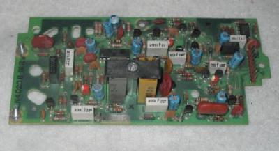
The HLN-4181 reedless board.
The long thin horizontal component at the bottom left is a TRN-4224 tone element that is plugged into the black socket under it.
The Mitrek DPL board 
HLN-4011
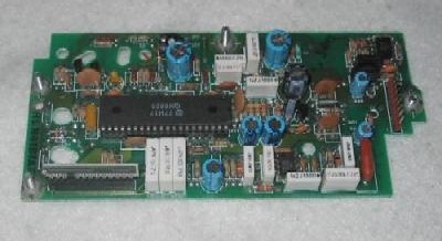
The HLN-4011 DPL board.
The long thin white horizontal component in the lower middle of the board is a TRN-6005 DPL code element that is plugged into the black socket under it.   Note that the TRN-6005 element is shorter than the TRN-4224 tone element and does not occupy all the pins of the socket.

In perusing the schematic of the HLN-4020 reed board I did notice one nice feature: it can be jumpered to use one reed for common encode/decode or two reeds for split tones.   I've not seen that feature in any other reed-based PL board.   When two reeds are used the encode reed is on the left of the hold-down bracket in the above picture with the decode reed on the right, when one reed is used it goes in the encoder socket and two jumpers are added.   The necessary jumpers are documented in the later schematics of the board (they are not included in the board revision D schematic but they are there are on the revision F schematic).   An early board can be jumpered for a single reed using the info from the later schmatic.

The rest of this section is focused on the HLN-4181 "reedless" PL board since I had six radios with five HLN-4181s, and only one of the HLN-4020 reed board.   Working for NASA for 6 years taught me that you don't put equipment into mission-critical service (i.e. on a mountaintop) that you do not have known good and ready-to-go spares for on the shelf.   In my opinion service trips should be limited to swapping entire units out, not fixing them on site (unless thatis the absolute last resort).   Especially if it takes you a couple of hours to get to the start of the dirt road, and another hour in 4-wheel-drive to get up to the radio site... and that's in good weather.

For more information on the HLN-4020 dual-reed board, the HLN-4181 reedless board and the tricks they can do, plus information on how to build your own TRN4224 tone elements please see my web page at http://www.repeater-builder.com/mitrek/mitrek-hln4181.html.

The HLN-4181 reedless board can be set up in several ways... The normal configuration of jumpers (and the most useful one) is listed in the table below... The board can run simultaneous encode and decode - the encode portion generates the PL tone continuously while the other half is able to decode PL at the same time.

HLN 4181 Reedless Mitrek PL Board Factory Jumpers
Jumper
JU-
Normal
setup
Function
1 OUT Normally used to couple the internal PL tone encoder to equipment outside the radio
2 OUT Disables the internal encoder when in place
3 IN In to couple internal encoder to the TX modulator (and remove JU7)
4 IN Install for "AND" squelch (and remove JU5)
5 OUT Install for "OR" squelch (and remove JU4)
6 OUT Install to disable PL decode (RX carrier squelch only mode)
7 OUT In to connect external encoder (fed from control connector pin 18)
to TX modulator (and remove JU3)
8 OUT In to disable reverse burst
9 IN When installed couples RX audio into the PL decoder
If your HLN4181 board has JU1, JU6 and/or JU7 in place, remove all of them.   If you want your PL decoder to work then JU9 must be installed.   If you want the PL encoder to work then JU3 must be installed and JU2 must be removed.

JU4 and 5 are redefined if the radio has the HLN4119 "Busy Light" option (very rare)... for more information see the footnotes on the receiver and control head schematics in the manual.   The radios that do have the busy light option have to be paired with matching control heads ("busy light" heads have an 8-pin IC installed into the only IC position on the circuit board inside the head).

A PL decode signal is available at the collector of Q1 of the HLN-4181 PL board, which is available at one end of the JU6 jumper.   This transistor takes the PL decode signal from the custom chip and inverts it before sending it to the audio mute transistor (located on the main board).   I used a length of insulated wire to run that signal over to the end of the JU1 jumper that feeds pin 1 of the 9-pin connector that connects the PL board to the interconnect board of the Mitrek.   The connections are pretty obvious when examining the schematic, and are easily traceable when looking at the actual circuit board.

You will need a monospaced font (like Courier) to view this diagram properly.

    +12v
     !           add this jumper
     R 94k   +----------------------------+
     !       !                            !
     +-------O -JU6- O--        --O -JU1- O---+------+ 
     !         (out)                (out)     !      !
 Q1  C                                        !      !
 --B                  to other  --O -JU7- O---+      !
     E                circuitry     (out)            !
     !                                               !
    gnd                                              !
              HLN-4181 PL board                      !
                                                     !
                                                     !
+--------------------<<------------------------------+
!                 9-pin PL Board
!               connector P3 pin 1
!
!                      L18
+---O -Ju3A- O------O -JU15- O---Pin 18 of the control connector
     (added)           (in)     

             Interconnect board
PL 
decode jumper
This is what the JU1 to JU6 jumper looks like.
You can also install it on the component side.

Note: On the interconnect board make sure that jumper JU3A is installed, and that JU3B and JU3C are out.. This connects the PL decode indication on pin 1 of the PL board connector to pin 18 of the control connector - requiring nothing more than a funny jumper on the PL board and a short jumper on the interconnect board.   Normally pin 18 is used to bring an external PL tone encoder (mounted in the control head) into the PL board - here we're using it to route the PL decoder logic level output to the controller by the same path.   I've seen other Mitrek modification web pages that use pin 18 for other things such as TX audio or COR, but I much prefer using it for the PL decode logic level -- it's just a "cleaner" mod (and besides there are four more pins to use).

WRONG!
WRONG !
RIGHT!
Above is a picture of JU3A and how the designer at Moto expected you to jumper it.   It's a cute, inventive and resourceful idea but those 1/4 inch tab connectors fall off in mobile service, even if you squeeze them very tightly and push them on. Personally, I bend up a piece of bare copper wire into a hairpin and solder one end to one side of the board and the other end to the other side.   I leave an air gap under each loop so I can clip an EZ-Hook™-style test lead to it.   I install a wire on the left side simply as a handy ground point (one side of JU3C is ground) for a VOM or an oscilloscope probe (as shown), the right side wire in this picture is the actual JU3A PL decode jumper.

Note that this voltage from the collector of Q1 is not a true logic level - it will drive the PL decode input of most repeater controllers just fine, but if you need a signal that goes all the way to ground - for example to drive a LED (perhaps in a control head) you'll need to add a driver transistor.   The version below provides an open collector output for the PL decode signal.   If the upper transistor has enough gain the lower transistor may not be needed (see above for the rest of the details).

    +12v
     !                     --O -JU1- O--------->>--- 
     !                         (out) !      P3 pin 1
     !                               !
     !                          +----+
     !                          !    !
     !               100k       C    !
     R 94k    +--------R----- B      !
     !        !                 E    !
     +--------O -JU6- O--       !    !
     !         (out)            !    C
 Q1  C                          +--B    two 2N4401, 2N3904, 2N2222, etc
 --B                                 E
     E                               !
     !                              gnd
    gnd              (available at several locations, one of which 
                      is one side of JU2, another is test point E3, 
                      a third is pin 9 of the PL board connector)

              HLN-4181 PL board

My first version of this setup used the plain jumper above, and drove an Scom 7K directly (which has a 2v threshold between the inactive and active states).   I added the transistor driver for the PL decode LED inside the control head.   My second version (above with the two transistors) was used on a home-brew controller that needed a PL decode signal that went all the way to ground.   The two transistors drove the controller and a LED just fine.

    +12v
     !
     +-----R-------+                --O -JU1- O--------->>----
     !    see      !                    (out) !      P3 pin 1
     !    text     !                          !
     !         +---------------------------------+
     !         !                                 !
     !         ! LED                     photo-  !  Opto-isolator
     !         ! emmitter             transistor !  with open 
     !         ! side                     side   !  collector
     !         !                                 !  output
     R 94k     +---------------------------------+
     !             !                          !
     !             !                          !
     +-------------O -JU6- O--               gnd
     !               (out)
 Q1  C
 --B 
     E
     !
    gnd              HLN-4181 PL board

If I were to do this over today I'd use the circuit above - I'd use the existing transistor on the PL board to drive the LED side of an open-collector optoisolator (effectively shunting the 94k resistor to the point that it pretty-much drops out of the circuit).   The resistor in series with the LED side (the one shown without a value) would have to be selected to pass enough current to turn on the opto-isolator's LED fully without going into overcurrent (check the spec sheet for the optoisolators LED).   The use of the optoisolator makes this circuit pretty universal.


Using a separate PL encoder with the HLN-4181
The design of the reedless board uses the encoder as the frequency reference for the decoder function, and as such it can't run split tones (i.e. different encode and decode tones).   If you need to run simultaneous split tones in a single duplexed radio you will have to add a second device, either a PL encoder or decoder.   Having done both, I can tell you that it's much easier to add an encoder.   I've used home-brew twin-T oscillators, Cetec-Vega 188's, Com-Spec SS-32s, TS-32s, SS-64s, and TS-64s (the SS-nn is the encode-only version of the equivalent TS-nn product).   The TS-32 series does not have reverse-burst (unless you use an RB-1), the TS-64 does.   There is more information on the
Com-Spec web page here at Repeater-Builder.

You will need a monospaced font (like Courier) to view this diagram properly.

The hookup is fairly simple:

Connect the audio output of
the separate encoder here ---------------------------+
                                                     !
gnd to here, -----------------------------------+    !
or or to one side of R2                         !    ! 
or to test point E3                             !    !
or to P3 pin 9                                  V    !
                                               gnd   ! 
Control                              P3              !   R27 
connector    L18                    Pin 1            V   22K
Pin 18 ---O -JU15- O-----O -JU3A- O--<<---+--O -JU7- O----R--+
            (both jumpers are on          !    (out)         !
            the interconnect board)       !                  !
                                          !                  !
                                          !                  !
      +----------------------------+      !                  ! 
      !                            !      !                  !
      V                            V      !                  !
  ----O -JU6- O--        --O -JU1- O------+                  !
        (out)                (out)                           !
     PL decode from previous section                         !
                                                             ! 
                                                             ! 
   alternate insertion point for PL encoder ---+             ! 
                                               !             ! 
                                               !             ! 
         R25 4.3K      R25 4.3K                V             !     C24
 -----------R------+------R------------O -JU3- O-------------+------C----- to filtering 
audio from         !               (normally in but          !    1.0uf    then to TX 
internal PL        !               but remove it when        !             modulator
encoder        Thermistor          using a separate          !
                   !               encoder - see text)       O <-- Test point E1
                   !
                   R  R29
                   !  6.2k
                   !
                   +-----O <-- Test point E3
                   !
                   +-----O <-- Pin 9 of PL board connector P3
                   !
                  gnd

Note that JU3A is on the interconnect board and JU3 is on the PL board.   JU7 is normally used with external PL encoders built into the control head - these feed the PL tone in via control connector pin 18 and JU3A and JU7 must not be in place in a duplexed radio if you are routing the PL decode signal out via Control connector pin 18 and JU1.

Before connecting the new encoder leave JU3 on the PL board in place and make sure JU7 is out.   Then key the TX and measure the existing encoder's audio level (AC voltage) at test point E1 and write it down.   Now remove JU3 and connect the new encoder's audio output to the R27 side of JU7.   Ground can be acquired from one side of R2 nearby, from one side of JU2, from test point E3 or from pin 9 of P3 (the 9-pin connector to the interconnect board).   Depending on what DC supply voltage your new encoder requires you can find filtered +12v on the wide trace that connects L3, C43 and R45, or you can get regulated +9.1v from the trace that ties pins 31 and 6 of the 40-pin chip together, or from the solder pad shown in the photo below.   With the AC voltmeter back on E1 you can now set the level of the replacement encoder to match the original AC voltage.   If you are running separate TX and RX radios you can also locate the external encoder outside the radio and use the interconnect board JU3 and PL board JU1 and JU6 and JU7 jumpers in the TX radio like they were intended...   Note that the above implementation will not have reverse burst, as that is generated inside the HLN-4181 board's custom chip.   If you need reverse burst you can use the external PL encoder that was designed for the Mitrek or Micor "System's 90" control head setup, or a Communications Specialists TS-64.   Here's Com-Spec's own writeup on the TS-64 for the Mitrek.   It's not oriented to using it as an encoder-only, but the encoder and reverse-burst hookup is quite relevant.

+9.1v DC on the HLN-4181 board
You can find +9.1v DC to power the external PL encoder in the empty solder-filled hole just above the pen (which slipped just as the flash fired...)

Test point E3 on the HLN-4181 board
Test point E3, pointed to by the pen, can be used as the ground connection for your PL encoder.


Repeat Audio In
Bringing TX audio (i.e. repeat audio) in from the outside world into the radio is simple because the Mitrek is a true FM radio and the actual modulation is done inside the channel element.   All we have to do is to tap and insert audio into the modulation line going to the element.   There is an easy way and a right way... Both take a 10uf audio coupling capacitor and connect it from the control connector's frequency 4 select pin through the RF protection choke to the modulation line of the transmitter channel elements.   The difference is where we tap into that modulation line.

TX Audio Test Point B
The easy way is to just patch a 10uf capacitor onto the interconnect board between JU9 / L10 and this plated through hole.

>----------------------------------------O -JU3A- O--+--O -JU15- O---Pin 18 of 
9-pin PL Board                              (in)     !     L18       the control 
connector pin 1                                      !               connector
                                      +--O -Ju3B- O--+
               JU9/L10        10uf    !     (out)
TX audio in     choke        -! !+    !
>-------------()()()()--------! !-----O <-- plated-through hole 
control head               ^  ! !     !      on interconnect board
connector pin 10           !          !      right below and in between 
                           !          !      JU3B and JU3C.
                           !          !
(Frequency 4 select)       !          +--O -JU3C- O <--- this is where I grab my VOM
lift the main-board side --+          !     (out) !      or oscilloscope ground
of the choke and connect              !           !
the new capacitor to it)              !          gnd
                                      !
                   interconnect board !
                                 ==========
                           main board !
                                      !      O "Point B"
                                      !      !
                                      +------+---- to TX modulator

The better way is to run one end of that same capacitor to the main board.   Find "Point "B" on the schematic and then on the main board near the mic audio circuit, look around Q1004, R514 and R501, it can be a little hard to find...   The "Point B" is preferred as connecting the capacitor there bypasses the connection beteween the interconnect board and the main board, which according to the Cactus writeup mentioned above "has been found to be the cause of intermittent and high resistance connections".   They aren't kidding.
Note: do not use a tantalum cap for the 10uf one mentioned above, they are bad news when used as audio coupling capacitors.

TX Audio Test Point B
The right way is to inject it into test point B, pointed to by the pen.   Don't be surprised that the hole in the PC board is big, it's sized for a push-on-pin.

This is the right way:

               JU9 / L10        10 uf
TX audio in    choke            -! !+
>-------------()()()()-----------! !-------- connect to 
control head               ^     ! !         "Point B" on
connector pin 10           !                 main board
(Frequency 4 select)       !                 (see text)
                           !
lift the main-board side --+
of the choke and connect the 
new capacitor to it

Note that the TX audio injected at the modulation line by either method shown above is NOT pre-emphasized by the TX audio circuits before modulating the radio.   If you need pre-emphasis you need to do it to the audio before it hits the radio.

In my case when the radio's dev pot is set properly and the repeat TX audio level out of the controller is adjusted properly the local mic audio is a little low - however if the local person "close talks" the microphone (with the lips just barely clearing the mic grille) and speaks at a level just a little above normal conversation level it is perfectly acceptable for test use.   As often as I go to a hilltop site and need to use the link radio's local microphone I can live with having to close-talk and "speak up" a little.

It is the authors opinion that having the repeat audio level be independent of the RX volume control, plus having a working local speaker and permanently installed local microphone jack on every radio in the system is very useful - it allows a local user to simply walk up to the rack, turn up the volume on any radio and monitor the frequency.   If needed he can pick up the appropriate microphone (or plug in a microphone) and talk just as he would expect to.


Carrier Operated Relay (COR)
Carrier Operated Switch (COS)
Carrier Detect (CD)
Channel Busy
   (you choose the term you prefer)

I seriously suggest you use the Link-Comm RLC-MOT board (as described below) to generate the COR and repeat audio outputs, but if you chose not to, then generating a logic-level signal that indicates open squelch isn't hard, but it does need one NPN transistor, maybe two, depending on your preferences.

To bring the COS signal outside (from either the RLC-MOT or from the added switching transistor) I lifted the radio end of JU7/L8 on the interconnect board leaving the choke between control connector pin 8 and the COS signal source.

   Original !  Added carrier
    Mitrek  !  detect circuitry
   --------------------------------      JU7 / L8 
            !                             choke         pin 8
            !         control        +---()()()()-----------<
            !        connector       !                  F3 select
            !          pin 4         !
            !           +12v         ! <--lift this end of the
            !            !           !    choke in the radio from 
            !            !           !    the existing circuitry
            !            !           !    and hook to new     
            !            !           !    transistor collector
            !       10k  R           !
audio    !  !            !           ! <--open collector COS out...
mute     !  !            !           !    low with squelch open / signal present
switch   !  !            !           C
Q406     C  !            +-------- B
    -- B    !            !           E
         E  !            !           !
         !  !            C           !  New transistors are almost
         +-------R----- B            !  any NPN silcon - 2N4401s,
         !  !   10K      E           !  2N3904s, 2N2222s, etc.
  R414   R  !            !           !
150 ohm  !  !            +-----------+
         !  !            !
        gnd !            !       pin 6 or 17 of the control 
                        gnd  <-- connector, or another 
                                 internal ground

Yes, the second transistor inverts the first and is not really needed, but I prefer open collector outputs from radios, and I prefer active-low signals between the radios and any external circuitry, especially repeater controllers.   Why? well, I prefer open collectors since most controllers have their own internal pull-up resistors, and a open collector output is therefore universal - it will work with a +5v logic system, a +12v logic system, relays, a LED (for testing), anything, and all with no modifications.   I prefer active low signals becasue if a radio loses power or otherwise fails, the controller doesn't "pull up" the dead signal to a false positive, resulting in the system being keyed until the timeout timer disables the system TX (you DO have a separate backup timeout timer, don't you?), thereby rendering the entire system unusable.   Also when you are working on the system you can do a large amount of testing with nothing more than a clip lead shorting the open collector outputs to ground without worrying that you're going to blow something up (picture a site visit some day... PL decode not working? gound the PL decode lead and see if the PL indicator on the controller front panel lights up.   yes? the problem's gotta be inside the receiver chassis!).   Also with open collector interfacing you can shut off the system, disconnect or un-cable the bad radio/device/etc. and then turn the power back on and everything else in the system still works because the unplugged open circuit looks like the idle open collector...

If you absolutely have to use a high going signal just leave off the second transistor and use this:


   Original    !  Added
   Circuitry   !  Circuitry      JU7/L8
               !                 choke         pin 8
               !            +---()()()()-----------<
               !            !                  F3 select
               !            ! 
               !            ! <--lift this end of the choke
               !            !    in the radio from the
               !            !    existing circuitry and hook
               !            !    to the new transistor collector    
audio     !    !            !
 mute     !    !            !
switch    C    !            ! <--open collector COS output...
Q406 -- B      !            !    high when squelch open / signal present
          E    !            !
          !    !            C
          +---------R---- B
          !    !   10K      E
    R414  !    !            !
 150 ohm  R    !            !
          !    !            !
         gnd   !            !
                          gnd

Note that the above COS circuit is in reality an open squelch detector and only works as a COS if you leave the radio's squelch circuit in carrier squelch mode.   We are deriving our COS signal from the audio mute transistor and for it to be valid we have to leave the RX in carrier squelch mode.   The PL board mod above brings the PL decode indicator to the outside world, but leaves it hooked to the main board audio mute circuit (I wanted to avoid as many radio mods as possible - to make the radio as "serviceable / testable" on a standard-wired test bench as possible).   This means that if you place the receiver into PL mode the audio mute transistor will be controlled by the combined COS and the PL decode signals (remember the "AND" and "OR" jumpers on the PL board?), which we don't want.   It is very desirable to be able to deliver separate COS and PL decode lines to your repeater controller, and depending on the capabilities of your controller you can run the system in carrier only mode, PL only mode, carrier AND PL mode, or in Carrier OR PL mode.   As a bonus some controllers (one is the Scom 7K) allow you to run the repeater in carrier mode while requiring all commands (touchtone) to have a PL tone - and if you want, you can have a command or two that doesn't require PL...

So leaving your Mitrek local speaker in carrier mode is a "So what?" type of a problem...   You are going to leave the radio volume control turned down to zero, and at a mountaintop repeater site nobody will be there to hear it anyway.   Forcing the receiver into permanent carrier squelch mode is easily done in several ways:

Personally, I do not like option 1 - it's not idiot proof from someone opening the rack and accidentally bumping a switch while doing something else.   I've used option 2 when I'm using stock cables, or option 3 when I'm building custom cables.   I leave JU14 / L16 alone so that the radio still works properly on the test bench.

If you use the RLC-MOT board to create your repeat audio out the discusion above is irrelevant as the Mitrek stock carrier squelch and RX audio circuits are completely bypassed.

Alternative Carrier Operated Relay circuits and points
Quite a few of the other Mitrek modification web pages tell you to use test point 'E' in the radio, or to take a COS signal from U401, pin 4, or from the PL board.
I'll describe those here...

All in all, if you are going to use the internal carrier squelch simply taking the DC voltage off the emitter lead of Q406 with a transistor inverter works the best for me.   It's simple, reliable, is guaranteed to work with any of the three PL / DPL boards, and the rest of the radio has no idea it's there.

After this web page went up I received an email from a friend that basically stated "Point 'E' works just fine for me.   Just connect a 15k ohm resistor to point E and use it like this:"   (his schematic below, you can add the extra transistor as above to generate a low going output signal):

 Original       !  Added
 circuitry      !  circuitry
----------------------------------
                !
         +9.5v  !
           !    !
           +-----------------+
           !    !            !
      R430 !    !        10K R
      82K  R    !            !          COS signal to 
           !    !            +--------- controller (9.5v high 
Motorola's !    !            !          with squelch open / signal present... 
point 'E'  !    !            C          You can leave out the 10k resistor 
    -----> +---------R----- B           for an open collector)
           !    !   15K      E
     Q406  C    !            !
     ----B      !            !    Transistor is almost any 
           E    !            !    NPN Silicon as listed above
           !    !           gnd
           !    !
           !
           !
           ! <------I picked my COS signal above from here
           !
     R414  !
     150   R
     ohms  ! 
           ! 
          gnd

Repeat Audio Out
I do NOT like methods that take audio out of the repeater receiver in such a way that the repeat audio level varies as the receiver's local volume control is adjusted.   It is my personal opinion that the repeater receiver volume control should be used for the local speaker volume, period.   This rule adds one more level of "idiot-proofness".   The method described below does just that.

Repeat audio out is actually pretty easy - just use a Link-Comm RLC-MOT board (described in the squelch / COS section).   But if you decide to "roll your own", it is a simple process as long as your repeater controller can mute the receive audio.   Just add a 10uf cap inside the radio between the discriminator to pin 9 of the control connector.   Note: do not use a tantalum cap here, they are bad news when used as audio coupling capacitors.   If your controller does not do the audio muting for you, like the ACC RC-85 and RC-96 models, you will have to add a series FET audio switch controlled by the COS, or use Link's RLC-MOT (which has it's own audio muting).

Here's the quick way - all of it is on the interconnect board:

From audio             +!!        choke     Pin 11    (Buffered audio out
circuitry -----------+--!!--------()()()-----< <----- to control head volume 
inside radio         !  !!      JU10 / L11            and squelch controls)
                     !  C3 
          (see text) ! 
                     ! Existing radio circuitry (C3 is located on the interconnect board)
      - - - - - - - -!- - - - - - - - - -
                     !
                     !  Added circuitry
                     !
                    +!
               10uf ---  <-- add this cap inside the radio
              at at ---
          least 15v  !
                     !
                     !     choke        Pin 9
lift this side ----> +----()()()---------< <------ audio to the
of the choke             JU8 / L9       Freq 2     controller 
from the radio                          select
circuitry

Here's the right way (which bypasses the main-board-to-interconnect-board connector):   Take the audio from pin 1 of U403A (which is an 8-pin opamp).   If you want to use shielded cable (I would) you can find ground on pin 4 of the same chip.   Note that this pin has about 600mv of audio on top of about 5.5v of DC on it.

>From U403 Pin 1 ----+
                     !  Existing radio circuitry (main board)
      - - - - - - - -!- - - - - - - - - -
                     !
                     !  Added circuitry
                     !
                    +!
               10uf --- <--- add this cap inside the radio
              at at ---
          least 15v  !
                     !
                     !     choke        Pin 9
lift this side ----> +----()()()---------< <------ audio to the
of the choke             JU8 / L9       Freq 2    controller 
from the radio                          select
circuitry

Note that in the two diagrams above the audio to the controller IS NOT de-emphasized, but in most cases it is not a problem as many controllers offer de-emphasis internally.   If yours does not, we can fix that:

                   !
                   !  Existing radio circuitry as above
                   !
      - - - - - - -!- - - - - - - - - -
                   !
             10uf --- <--- add this cap inside the radio
            at at ---
        least 15v  !
                   !
                   \
                   /
                   \  15K ohms, a magic value, do not substitute
                   /
                   \
                   !
                   !     choke         Pin 9
                   +----()()()----------< <------ audio to controller 
                   !   JU8 / L9        Freq 2     (must be a high-
                   !                   select      impedance input)
                   !
                  ---  0.1uf, a magic value, do not substitute
                  ---  and do not use a tantalum cap
                   !
                   !
                  gnd  <---  pin 2 of the control connector (audio ground)
                             or pins 6 or 17 some other internal ground

On the other hand, in the diagram above the audio to the controller IS de-emphasized.   The overall audio level will also be lower than without the de-emphasis circuitry.   For more information on the "magic values" in the schematic above and how to calculate them, see the excellent article by Matt Lechliter W6KGB at http://www.repeater-builder.com/rbtip/pdemph.html.   In the above diagram the repeater controller must have an input impedance greater than 150k (calculated as 10x the 15K resistor above).   High impedance inputs can be RF sensitive, make sure you use shielded audio cable for this connection - I use RG-174 as audio cabling in my repeaters.   It's regular 50 ohm coax, and while it is lossy at VHF and UHF frequencies it's perfectly OK at audio. Besides it's not expensive, it's readily available, small, has a tight shield and is very flexible.

Note that the Mitrek has a PL filter on the PL decoder board, unfortunately it is positioned in the RX audio stream after the volume control and it is a notch-type filter.   Ideally it would be a high-pass filter located before the volume control so that the repeat audio would have the PL filtered out, but it's not.   Several folks have tried to use the internal filter in repeat or link service, and the performance leaves a LOT to be desired.   The overall consensus is that it's not worth even trying.   Some folk disable the on-board PL filter to eliminate any modification of the received audio - just remove C38 on the PL board (if you are careful as you remove it you can reuse it in the audio de-emphasis circuit above).   If you need a high-pass PL filter it's easy to add an outboard PL filter between the Mitrek RX and the controller.   An excellent one can be found at http://www.ka9fur.net/w9hhx-io-pg4.jpg.   Leave out the ID notch filter unless you need it.   There are two more at http://www.repeater-builder.com/pl-filter.   If you want to you can place the filter in the audio line in place of JU10 / L11 on the interconnect board, or externally between the radio and the repeater controller.   If you place the PL filter at the JU10 / L11 point you will want to relocate the repeat audio output pickoff point to after the filter.


Comments on the Mitrek Carrier Squelch
Modern FM radios utilize a noise operated squelch which works by measuring the amplitude of the discriminator white noise at the audio frequelcies above the frequency range used by the human voice.   Speech lives in the range from 300hz to a certain point, above that is all noise.   The cutoff frequency between what is considered voice and what is considered squelch noise is critical: too low and the squelch will chop on higher pitched voices, too high and there won't be enough high frequency noise to work with (the top frequency of the available noise is controlled by the IF bandwidth).

Imagine a RF generator connected to the RX, the squelch is wide open, and an AC voltmeter connected to an audio dummy load hooked across the the speaker leads is showing a volt or two of noise.   As you slowly increase the level of an on-channel dead carrier, the level of squelch noise quickly lowers with just a little bit of signal.   If you reduce the carrier level the noise comes back up.   Receiver sensitivity is measured this way, look for the "20db quieting" measurment in a radio specification sheet (and some point-to-point links - especially voting RX links - need 30, 35 or even 40db of quieting).   The noise operated squelch circuit takes this high frequency AC noise and amplifies it and rectifies it into a DC voltage that varies with the noise level.   When this DC voltage drops below a specific threshold (set by the squelch control) the speaker unmutes, and as it rises above the threshold the speaker mutes.   Most modern radios use two different thresholds (the difference is called the squelch hysteresis amount), one level for squelch open, and a slightly lower one for squelch close.   This improves how the user preceives the squelch action: once the squelch opens the signal can drop back past the squelch-open threshold level and then drop a a little more before it closes.

Many people are dissatisfied with the stock Mitrek squelch, especially if thy have ever been exposed to a Micor or a GE Mastr-II.   The typical complaint is that that the squelch threshold level (to stop the white noise in the speaker) is much lower than the level required to eliminate the random "cracklies" caused by on-channel noise spikes.   In other words to get a totally quiet receiver the Mitrek squelch control has to be set much higher than the initial squelch-closing threshold - in some cases turning the squelch control all the way to the top isn't enough.

The reason for the poor performance of the Mitrek carrier squelch circuit is inherent in it's overall design.   The entire circuit uses only only five transistors.   The Mitrek came into being in a era where the use of PL or DPL was universal, and carrier squelch had gone by the wayside.   Motorola installed a simple noise operated squelch, and it almost seems to have been included as an after thought.   The designer didn't put much time or thought into it, knowing that it wouldn't be used much...

In contrast, Motorola put a great deal of effort into the Micor's noise squelch circuit since the use of PL and DPL had not become universal at the time of the Micor's design.   In short, the Micor was the high water mark for carrier squelch circuit development - the heart of the Micor carrier squelch circuit is a single custom IC chip which contains over a hundred transistors.   Unfortunately this part is obtainable only as a spare part from Motorola or by carefully scavenging it off of a Micor audio-squelch board (and it was not socketed).   The Micor squelch chip is a complete bi-level or switched hysteresis squelch system on a single chip.   Simply, the Micor bi-level squelch works better than anything else on the air.   Note that the circuit could be added to any model radio - even the Metrum-II.   In fact, it's not hard to hook an inexpensive Micor mobile Audio-Squelch card (available for $5 or so) to almost any radio that has raw discriminator audio and positive 9.6v DC voltage available.   A 25k squelch pot completes the circuit.

Naturally, when a need shows up, somebody fills it for a price.   Link-Comm makes a line of repeater controllers and they have an accessory board called the "RLC-MOT" that will add a Micor squelch into any receiver that provides raw discriminator audio.   The board will fit inside any mobile radio and is much smaller than the actual Micor audio-squelch board, works great and makes the squelch action a lot more pleasing, and eliminating the squelch tail the stock Mitrek creates.

The Link-Comm RLC-MOT module
The Link-Comm RLC-MOT module is small,
only 2.5 inches by 1 inch

The RLC-MOT interfaces with a single six pin connector (pin 6 is nearest the corner of the board):

RLC-MOT pinout
PinFunction
1+11 to 15vDC at about 35ma
2Discriminator audio in
3Buffered and muted audio out
4Active low COS
5Active high COS
6Ground

The RLC-MOT uses a trimpot for an on-board squelch control (a 20 turn!), has a LED that lights when the squelch is open, and and has an audio level pot on board.

If you are using an RLC-MOT module and need a de-emphasized repeat audio output you can take advantage of the fact that the option of de-emphasizing the audio was designed into it from the start - just add a capacitor across R9 on the module itself.   There are solder pads for it already in place (labeled C18).   They are small and you will have to use a very small cap and a very small soldering iron, and work quickly and carefully but they are there.   Depending upon the audio response you'd like to see, the cap should be somewhere between .0075uf (breakpoint at about 200hz) to .022uf (breakpoint at about 75hz).   While you can tailor it to suit your desires of low-frequency response the lower you go in frequency the less "effective gain" you will achieve due to the modification of the buffer/amp circuit's frequency response. A 0.01 cap will give you a breakpoint of 150hz,which is likely the best compromise.   The RLC-MOT is available from Link Comm at 800-610-4085 for about US$60.   Yes, I know, you spent less on the entire radio.

A quick-and-dirty hookup of the RLC-MOT to a Mitrek - NOT RECOMMENDED:

+-------------------+
!     Function  Pin !
!                   !
!          +12   1  !------ +12v
!                   !
!     Audio in   2  !------ See text below
!                   !                       choke
!    Audio out   3  !---------------------()()()()------< <--- repeat audio out to controller 
!                   !                      JU8/L9      Pin 9 - Freq 2 select
!  Low COS out   4  !---------------+                
!                   !               !      choke
! High COS out   5  ! unused        +-----()()()()------< <--- Active-low COS out to controller 
!                   !                      JU7/L8      Pin 8 - Freq 3 select
!          GND   6  !--+
+-------------------+  !
                       gnd  <-- pin 6 or 17 of the control connector, or
                                any other internal audio ground

Audio to feed the RLC-Mot can be derived from two places: purists can take if from pin 1 of U403A in the receiver, bypassing the main-board-to-interconnect-board junction (suggested) or from the radio side of JU10/L11 (which feeds pin 11 of the control connector).

When you mount the RLC-MOT make sure you do it so that the on-board LED is visible.   Double-sided foam tape works fine. You will need to get to the squelch adjust pot (labeled R3), the audio level pot (R14) and to see the squelch LED (D1).

Here's the right way to do it:
I really suggest that you use the "High COS Out" signal to drive an open collector transistor as shown below, with the collector going to the outside world via JU7/L8/pin 8.   Doing this will protect the RLC-MOT module from any errors in hookup outside the radio - I'd much rather toast a 25 cent transistor than a $60 module... the transistor takes the heat, so to speak.   If I were to do it over today I'd use the RLC-MOT to drive an open collector opto-isolator instead of the open collector transistor.

                                          choke         pin 8
     pin 2 ! audio in                +---()()()()-----------<
           !                         !    JU7/L8        F3 select
     pin 3 ! audio out               ! 
           !                         ! <--open collector COS output...
     pin 4 ! Low COS out             !    low when squelch open / signal present
           !                         C
     pin 5 !-----------R---------- B
           !         4.7K            E
           !                         !
           !                         !
                                    gnd

More info on the Micor squelch is at:


Duplexing / Dual Radios / Interconnections
Duplexing a UHF Mitrek can be tricky, and in many cases is frequency dependent (i.e. it will work on some frequencies and not on others).   The 406-420mhz models will spur if duplexed (please read the entire Cactus Radio document mentioned at the top of this writeup) and since I had two Mitreks and four Mitrek Plus radios on hand for the project I elected to just use two of the Plus radios for my full duplex point-to-point link.   Using two radios also meant that I didn't have to do the standard "duplex mod" (see below).   As my long-term plans were to replace the two 440mhz Mitreks with 420mhz ones, I had to use two radios anyway.

One additional mod I made to the control head that when first described makes people wonder why: I shorted out the double pole power switch on the control head volume control with two individual jumpers and added a label to the front of the control head that says "Control head power switch bypassed - Use power switch on Astron to turn link radios on and off".   Why?   I made the change and added the label after I turned the volume down a little too far as I was leaving the site on Sunday night and killed the link... it was dead for a week until I could get back to the site and turn the switch back on.   It was very frustrating - a one and one/half hour drive just to get to the start of the 4-wheel-drive dirt road, then another hour to get to the radio site.   Out of the vehicle for long enough to open the building door, disable the alarm, flip a switch, test the link, re-enable the alarm, lock the door, then 2 and 1/2 more hours to get back home.   On my next visit I jumpered the switch out and added the label.... adding one more layer of "idiot-proofness".   Phil Lefever, KBØNES made the point quite well in an email when he said: "I hate driving up the hill to fix something I could have done better the first time around".

Here's a crude diagram of my dual radio cabling - it makes two Mitreks look like one single full duplex radio:

                            big wire                 big wire
                 +--------------------Big Fuse------------------------+
                 !                                                    !
                 !          big wire                                  !
                 !  +------------------------+                        !
                 !  !                        !                        !
 +--------+      !  !     +--------+         !   +----------------+   !
 ! Pin 19-!------+  !     ! Pin 19-! open    !   !     Astron     !   !
 ! Pin 17-!---------+     ! Pin 17-!---------+---!Neg  power   Pos!---+
 !        !               !        !             !     supply     !   !
 !        !               !        !             +--------------- +   ! 
 !   TX   !               !   RX   !                                  !
 !  plug  !               !  plug  !                               7a fuse
 !        !               !        !                                  !
 !        !               !        !                                  +---+
 !  see   !               !  see   !                                  !   !
 !  note  !               !  note  !                  +----------------------+
 !  #10   !               !  #10   !                  !          pin 19   20 !
 ! below  !===============!  below !==================!                      !
 +--------+   control     +--------+  control         !  Mitrek single-freq  !
              harness                 harness         !     control head     !
                                                      ! with bypassed power  !
            to                                        ! switch and LEDs for  !
         repeater ------>>----------------------------!    COS, PL decode,   !
         controller    DB15      Ribbon cable         !    power and PTT     !
                                  (see text)          +----------------------+
                                                        !         !
                                                        +-- mic   +-- speaker

To connect the two radios to a single control head I took two old Motrac cables (Mitrek, Motrac, Mocom 70 and some of the earlier all-tube vintage radios all used the same connector but with different wiring).   The control harness in the drawing above was built up by starting with a control cable that had been cut during removal (C. W. Wolfe sells these for a very reasonable price).   I took the control head end with the numbered pin connectors which gave me some nice long leads and then scavenged the radio end connectors off of both cables.   This gave me two connectors, two sets of connector shells and a full set of pinned and numbered leads about 5 feet long.

The leads to the radio connectors were cut to length as I added each wire to the harness.   I wired everything up using the recycled numbered leads so I had a RX radio and a TX radio on one single frequency control head (i.e. no frequency switch)... see the detailed diagram below.

To connect the dual radio assembly to the repeater controller I cut a slot in the back of the control head to allow a piece of 15-conductor flat ribbon cable to exit out of the head.   The actual DB15 connector and ribbon cable I used came off of a game port connector plate from an old combination I/O card from an ISA vintage PC.   I cut off the 16-pin header connector and separated the individual leads for a few inches and stripped the insulation off.   To get the ribbon cable out of the head I drilled two holes with a 1/8" drill bit just far apart to clear the cable and used an old soldering iron with a long thin concial tip that just fit into the 1/8"hole and dragged it sideways to melt the plastic between the two holes.   Moto used good thick plastic, it took a while to do it and do it with good ventillation.   I don't have access to a milling machine but if you do then you could duplicate that slot much faster or even mount a DB-15F into the top or front of the head itself... above the area where the frequency switch would go is one good place....

The overall radio-control head harness consisted of all the pinned cable leads that were required plus the two large power cables, all tied together with a piece of 3/8 or 1/2" (I forget which) spiral wrap (from the local auto parts store) that started with the power wiring and the TX connector on one end, the RX connector in the middle, and the control head and controller DB15 connector at the other. If you are not using a control head then you could mount a pair of miniature volume and squelch pots and a couple of LEDs in the connector shell itself.

The table below is the pinout of the DB15 that goes from my dual Mitrek lashup and the controller.   The first 7 pins are the same as a Link Comm controller, pins 8, 9 and 10 are unused, the last 6 pins are my own wiring.   I relocated the audio grounds to pins adjacent to the audio pins since the the overall construction was much cleaner.
1 Logic Gnd DB-15 connector pinout
8   7   6   5   4   3   2   1
-----------------------------------
\  O   O   O   O   O   O   O   O  /
\  O   O   O   O   O   O   O  /
 -----------------------------
 15  14  13  12  11  10   9
View from the surface of
the female connector that accepts
the male plug, or from the wiring
(back) side of the male connector.
2 PL decode output
3 TX PTT in
4 TX audio in (shield to pin 11, Link-Comm has shield to pin 8 of a DB-9)
5 RX audio out (shield to pin 12, Link-Comm has shield to pin 9 of a DB-9)
6 Logic Gnd (see note 9 below)
7 RX COS/COR out
8 Reserved for future use
9 Reserved for future use
10 Audio Gnd (TX audio shield)
11 Audio Gnd (RX audio shield)
12 Link RX power monitor (see note 6 below)
13 Link TX power monitor (see note 5 below)
14 PL encoder disable
15 Reserved for future use

Here's a pin-by-pin detail on the wiring I used - but refer to the manual so you completely understand it before trying to duplicate this:

                  TX         RX       Control
             radio pin    radio pin   head pin
                  1 ------------------- 1 see note 1
     +----------- 2 --------- 2 ------- 2 see note 1 and note 12
     !<--note 14A
     !       +--- 3           3 ------- 3 speaker hot   8.2k  4.7k
     !   +-->R    4 --------- 4 ------- 4 --------------R--+--R------gnd   see note 6
     !   !   +--- 5           5 ------- 5 speaker hot      !                               
     !   !        6 --------- 6 ------- 6 see note 10      +- DB15 pin 13 (link power on)
     !   note     7 ------------------- 7 see note 7 -------- DB15 pin 15 (PL encode disable)
     !   2 and                8 ------- 8 see note 7 -------- DB15 pin 7 (COS out)
     !   14C                  9 ------- 9 see note 7 -------- DB15 pin 5 (RX audio out) note 9
     !           10 ------------------ 10 see note 7 -------- DB15 pin 4 (TX audio in) note 9
     !  note +-- 11          11 ------ 11 see note 3
     !   14B !   12 ------------------ 12
     !    -->!   13 ------------------ 13 ------------------- DB15 pin 3 (TX PTT)
     !       +-- 14          14 ------ 14 see note 3
     +---------- 15          15 ------ 15 see note 3
                             16        16 see note 4
Ground --------- 17 -------- 17 ------ 17 ------------------- DB15 pin 1 and 6 (Logic Ground)
                             18 ------ 18 see note 8 -------- DB15 pin 2 (PL decode out)
+13.8vDC --+                       +-- 19 +12 from Astron
           !                       !
           +-- 7A fuse ------------+-- 20 +12 from Astron
           !                           21 see note 3 -------- DB15 pin 11 and 12 (audio ground)
          Big             +------------22 see note 5 -------- DB15 pin 14 (link TX power on)
          fuse            !
       (note 11)          !         +--24 \
           !              !         !      See note 15
           !              !         +--27 /
           !              !
           !      TX      !     +----- 29 or 31               DB15 pins 8, 9, and 10
           +----- 19      !  RX spkr                          are reserved for future use
           !              !     +----- 32
          8.2k  Note 5    !
           !              !
           +--------------+     NOTE - all unreferenced or not shown pins on the RX, 
           !                           TX and Control head connectors are not used 
          4.7k  Note 5                  and are left floating.
           !
          gnd
Notes:
  1.  TX pin 1 and 2 is a shielded cable with the shield connected to pin 2.   Pin 1 is mic audio, 2 is audio ground.
  2.  TX pins 3 and 5 have a 47 ohm 1 to 2 watt load resistor connected to them (a dummy speaker load).
  3.  RX pins 11, 14 and 15 are shielded with the shield hooked to pin 2 on the radio end and pin 21 on the control head end (audio ground).
  4.  RX pin 16 normally connected to control head pin 16 to allow the control head "Monitor" switch to set the RX into PL or carrier mode. By leaving the pin 16 unhooked the PL decoder can never accidentally be enabled.
    I personally do not solder a wire to the pin and in fact put a piece of heatshrink over the RX connector pin 16.   This heat shrink on the bare pin is a memory-jog trick I learned at NASA in the 1970s - it tells you (and the next guy) to check the documentation before doing anything with that connector pin.
  5.  These two resistors are optional... You could put them on the back of the TX connector from pins 19 to 17 and connect the center point to a lead plugged into pin 22 of the control head and from there to a DB15 pin tied to a spare digital input on the controller.   Pin 22 of the control head is normally hooked to pin 6 of the PL switch (the one labeled "Monitor") and you can cut the trace behind the switch and use the adjacent plated-through hole to connect the DB15 cable lead.   The two resistors divide the power supply voltage to a logic high, i.e. about 4.5 to 5v. If the big fuse blows the controller digital input will go low and the controller can announce "No power to link radio TX" when you switch on the link...   (if you have a leftover digital input, you might as well use it for something interesting until you need it for something useful).
  6.  If you have a second spare digital input just duplicate the two resistors but put them either inside the RX radio connector shell from pin 4 to ground (pin 6 or 17) or put them inside the control head from pin 4 to ground (pin 23) and either way run the center point to the the controller digital input, and program the controller to say "No power on link radio RX".
  7.  Pins 7, 8, 9, 10 are normally hooked to the control head freqency switch. If you use a single freq control head (without a switch) the virgin solder pads for the switch can be used as tie points for the leads from the DB-15 cable.   Or you can take a multifreq head and remove the switch.
  8.  Pin 18 is normally hooked to pin 4 of the PL switch and you can free it up by cutting the trace behind the switch and use the adjacent plated-through hole to connect the DB15 cable pin.
  9.  Both DB15 pins 5 and 6 are hooked to audio coaxial cable (I used RG174 simply becuse I had a spool of it on the shelf - it's lousy UHF coax but great as audio cable) with the shields grounded to control head connector pin 2 on the head end and to DB15 pins 8 and 9 on the other.
  10.  Pins 17 and 19 of the TX connector are the TX high current pins and should connect to the Astron with heavier gague wire.   For a low power radio (T2xJJA, T3xJJA or T4xJJA model numbers) you want to use at least #12 wire, and #10 for any higher power radio (the T5xJJA, T6xJJA, T7xJJA, T8xJJA series). Use the next larger size wire for any run over 10-12 feet.   Pin 17 of the RX connector is tied to pin 17 of the TX connector and to pin 17 of the control head but that can be done with smaller gague wire to the RX-only radio.   Make sure that you jumper pin 6 of the TX and RX connectors to pin 17 at each connector.
  11.  The size (amperage) of the "big fuse" depends on both the TX power level and the frequency band.   See the Motorola manual for your radio for the proper fuse rating.
  12.  DB15 pin 11 and 12 (audio ground) can be connected to either pins 2 or 21 in the control head, or pin 2 on the control connector on either radio - whichever is easier for you.
  13.  The above drawing does not show the internal mods to the radios (like installing JU611 forcing the frequency 1 channel elements on).
  14. Inside the TX radio connector:
    1. The volume control is replaced with a jumper from the wiper pin (pin 15) to ground (pin 2) thereby setting a virtual volume control at zero.
    2. The squelch control is replaced with a jumper from the squelch wiper (pin 14) to the hot side (pin 11) thereby setting a virtual squelch pot at maximum.
    3. Connect an 47 ohm 1w or 2w resistor across the speaker leads (pins 3 and 5) and don't ground either of the speaker pins!!! The Mitrek runs both speaker leads hot and you will let the magic smoke out of your radio if either speaker lead is grounded.   If you are going to recycle an older cable or control head just assume that they ran a gounded speaker and trace both speaker leads from one end to the other and find those grounding jumpers and remove them. Better yet, strip both control cable connectors of all wiring and start over.
  15. This jumper is required if you are using a factory Mitrek PL board and want to use the PL decoder in the receiver.

Note that some control cables have a wire on pin 7 but do not have any on pins 6, 8, 9 and 10 (i.e. they are the "single frequency" cables) so chose the cables that you intend to chop up carefully.   I first found this out the hard way, back when I had a 4-freq 6m Motrac, a 6-freq 2m Motrac, a 4-freq 440mhz Motrac and a 4-freq U43MSN Motran modified for 220mhz in my 1971 Ford Falcon station wagon... the 2m Motrac cable ended up with a length of 10-conductor stranded intercom cable taped to it... the conductors made up for the missing ones in the control cable plus provided for frequency 5 and frequency 6 plus a couple of spares for TX PL tone selection.

Duplex Mod For The Mitrek
If you chose to use one radio and duplex it, you'll need to do these steps (do not duplex a 406-420mhz radio, especially if it will be going to a hilltop!!! For the reason read the Cactus Radio writeup mentioned above):

  1. Jumper the F1 elements to run full time using JU611 as mentioned above.
  2. Clip one side of CR403 (in front of L208).   This prevents the receiver's audio amplifier (i.e. the speaker) from muting when PTT is keyed.
  3. Clip one side of CR1 (near Q1004, in front of L702).   This prevents the RX channel element from shutting down when PTT is keyed.
  4. Give the RX and TX their own RF ports.
    • The mechanically simplest method I've seen is to disconnect the antenna relay coil wires from the motherboard and leave them floating, thereby using the front panel antenna port as the permanent receive antenna connection.   If you want optimum performance you can replace the front antenna connection with a female-to-female type N bulkhead connector (which will require enlarging the hole in the front panel) and then using double-shielded cable to the RCA connector on the RX chassis (scavenge the old RCA plug for reuse unless you have some of the short-center-pin plugs in your junk box).   I've also seen a female-N-to-female-SMA bulkhead connector mounted in the front of the radio with a male-SMA-to-male-RCA cable used to connect to the RX.   Either way, you will want to use high grade double shielded coax on the RX port (I prefer RG-400).   I've even seen a scrap of small diameter Superflex used here.
    • Next, you have to give the TX it's own port.   One way is to mount a double-female-BNC bulkhead connector in the sidewall of the radio.   Then cut the transmit coax at the back side of the antenna relay and solder or crimp a BNC male to it, then plug it into the new connector.
    • Probably the prettiest dual antenna jack mod I've seen is shown below this paragraph.   Not visible is the back side of the plate that replaces the stock antenna connector.   This plate mounts two female-to-female SMA bulkhead connectors, and the two new cables that run from the RF decks to the front panel have SMA male plugs to connect to that plate.   This makes for the best shielding and minimum RF leakage.   Unfortuntely this method requires enlarging the hole in the front panel to clear the two SMA connectors, and milling machines are not in the workshops of most hams.
    • Motorola made some Mitrek-based high band mobile extenders by leaving the final transistor out of the PA deck, and below are four photos of how Moto modified the PA deck and how they did the TX antenna jack... they mounted a SO-239 into the low power heat sink (looking at the heat sink end of the radio it's on the right side).   This mod would not be hard to duplicate, but again, milling machines are not in the workshops of most hams.

      Inside the PA deck.   You can see the driver transistor under the red capacitor, and that the final transistor to the right of the driver has been replaced with a metal strap jumper.


      The right side of the back of the full duplex Mitrek radio showing the TX antenna jack


      A long shot of the inside of the PA deck showing the back of the TX antenna jack


      A closeup of the inside of the PA deck showing the back of the TX antenna jack
An addition to step "D-1" above that also adds a PTT indicator to the front of the Mitrek (for those folk that don't use a control head) is to cut the two coil wires at the antenna relay (instead of disconnecting them from the main board), and then hook them to a red LED and current-limiting resistor in series, and push the LED into a snug fitting hole drilled into the front panel of the radio.   The top right corner of the serial number tag is a good place for the LED - there's just enough room inside the chassis for two or even three LEDs vertically along the right side of the handle... One could be a green LED for a power indicator, a red one for PTT... (or a single two-color-three-lead LED for both).   To locate the LED holes just latch the handle up and in place (as if the lid was on and the radio was in it's tray) and drill the top hole in the pocket formed by the top right corner of the handle.   Watch where the metal chips go, a good start is to drill the radio front panel with the radio upside down on the bench.

Another take on duplexing by N3EUA can be found at the TAPR website at http:// www.tapr.org/~n3eua/hw/mitrek.html.   It's oriented towards packet but it's still relevant.


Status Indicators
I used a single freq control head, and for status indication I mounted LEDs in the top of the head for COS and PL decode.   I replaced the two incandescent bulbs in the head with red and green LEDs just for consistency.   This gives me 3 LEDs in the top of the head: green for power, red for TX PTT, and a three-wire red/green for COS and PL decode.   Someday I may add a blue LED for PL encoder disable (that feature was added to the radio after the control head work was complete).   On an incoming signal without PL the dual LED glows green, and if PL is present it momentarily glows green showing the presence of the carrier, and when the PL decodes the red comes on with the green making amber to make it evident that both are present.   There is no reason I used a 3-wire 2-color LED except that I had a few in the junk box.   Two individual LEDs for COS and PL decode are just as easy.   The PL decode signal from the one-jumper mod above (JU6 to JU1) is a logic level as opposed to an open collector, I added an open collector driver transistor in the head to drive the PL decode LED.   I showed the open collector transistor in the PL decode section above as that's how the most recent radio was done.

The resistance rule of thumb for a 10ma led is 100 ohms per volt, so a 1.2k resistor in series with each LED is just about right for 12-13v, but the value is not critical - a 1k or 1.5k will work just as well.   For 20ma leds (the most common) use 50 ohms per volt, so 560 or 620 ohms is appropriate.   For 2ma LEDs I use 4.7k or 5.1K...   Whatever value you pick, use that value on all the LEDs so the light intensity is the same - except on the blue LED.   One characteristic of blue LEDs is that most of them take a little more current for the same intensity (they are not as efficient) so if you use blue you may have to use a little less resistance to get it to look right.   This is one place where an old Heathkit resistance substitution box comes in handy.


Mounting
To mount the radios in the system rack cabinet I bolted together a "sandwich" of two Mitrek mobile mounting trays and a thick steel rack shelf we found in surplus.   On the top of the shelf is the TX radio, under the shelf is the RX radio upside down. An Astron SS-25 is mounted adjacent to the TX Mitrek, and a control head bracket is bolted below to complete the assembly.   The sizing is perfect, you'd think that Astron designed the SS-25 specifically to fill the leftover space in the rack shelf.   When lifting the assembly by the ends the shelf started to "bow" in the middle due to the weight, so I added two pieces of right-angle steel stock, one at the front and the other at the rear of the shelf, both running the full width of the shelf.   The spacers in the drawing below are 1" long pieces of half-inch EMT conduit (only because I had a short length left over from a remodeling project) - lengths of a dowel with a hole drilled in the center or even stacks of washers would work just as well and are there only to allow the front of the lower radio to clear the front right-angle steel bracing when inserting it into or removing it from the mounting tray, and to allow access to reach the control head knobs and to see the LEDs.

The Astron is mounted to the shelf with long ty-wraps that extend through two holes drilled in the tray (at the "X" in the diagram below), across the bottom of the shelf, around and up the right side and back across the top of the supply.   Yes, I could have opened the Astron and drilled a couple of holes in the bottom to mount it, but I didn't want to affect the warranty, and I wanted to be able to swap it out without having to pull the rack shelf out of the cabinet.   The rack shelf I used is the exact height of the Astron, and the long ty-wraps (I used a couple of leftover riot handcuffs) work just fine.   A speaker bracket is mounted to the bottom of the rack shelf behind the control head.   The speaker lies flat against the bottom of the shelf with the speaker facing downwards.

  +------ rack mount shelf ears and mounting holes -------------+
  !                                                             !
+---+ +------------------------------------+ +--------------+ +---+
! O ! !                                    ! !   Astron     ! ! O !
!   ! !       TX Mitrek                    ! !    SS-25     ! !   !
!   ! !                                    ! ! power supply ! !   !
! O ! +----+--------------------------+----+ +--------------+ ! O !
+---+------!--------------------------!-----X---!----------!--+---+
        spacer - see text          spacer     spacer    spacer
      +----+--------------------------+----+ +--+----------+--+
      !                                    ! !     Mitrek     !
      !    RX Mitrek                       ! !  Control head  !
      !    (mounted upside down)           ! +----------------+
      +------------------------------------+    with speaker 
                                               mounted behind 
                                              the control head 
                                              facing downward

Second Receiver Concerns
There may be times when you want to put a second Mitrek-based link into your system, or perhaps you already have an existing radio with a 10.7mhz IF in your rack. Well, Motorola has come to the rescue with the MSR-2000 repeater.   The Motorola MSR2000 and the Mitrek share a common history.   In fact you could really stretch and say that the MSR is a base station version of a cross between the Mitrek and the Micor.   While the Mitrek is a single-board "unified chassis" design, the MSR uses separate RX and TX boards, a control shelf, and other non-mobile features.   Despite this there are many common components.   One of these is the receiver IF crystal filters.   The normal Mitrek and MSR-2000 IF frequency is 10.7mhz.   When there is a second receiver in the same cabinet the second receiver IF needs to be moved to a different frequency to avoid in-cabinet interference.   If you put a second Mitrek based link in a system cabinet and have an interference problem you can move the IF of the second RX by re-ordering the channel element crystal for a 10.8mhz IF, installing the 10.8mhz IF filters and realigning the RX.   The part numbers for the 10.8mhz filters are (thanks to WA6KLA for the information): Y201 is a 48-84396K07 and Y202, Y203, Y204, Y205, Y206 are all 48-84396K06.   If you do convert a mobile to a 10.8mhz IF PLEASE leave a note inside the radio and on the front of the radio - maybe use a big Sharpie pen on the sides of every IF can and write "10.8 IF".   The next guy who gets to recrystal that radio will appreciate it!


Closing notes
The dual Mitrek assembly described above is currently used as a single channel full duplex UHF point-to-point link in our UHF repeater system.   The main repeater is on controller channel 1 and the dual Mitrek is on channel 2.   The reason for the use of dual radios is that the initial implementation used 450 Mitreks tuned to the regular user input and output frequencies of the far-end repeater, later replaced by 420 Mitreks on real link frequencies.

Setting the receiver frequency can be a bit tricky as the Mitrek uses a quadrature detector rather than a ratio detector or a crystal discriminator, therefore there is no "Motorola standard Metering Point #4" zero-center test point.   The Mitrek designers added a circuit to help tune with a zero-center meter, but I've found that using a SinAdder gives me better results.   If you don't have one, sometimes the simplest way is to use a frequency counter with the hot side of the test probe hooked to pin two of the channel element socket.   Just remember to compensate for the 10.7mhz IF frequency.   Then start looking for a Sinadder - maybe on eBay - they aren't that expensive and are a valuable addition to your test equipment collection.

Remember that the Mitrek mobile transmitter was not designed to be a 100% duty cycle transmitter.   In fact, Motorola states in the manual that the Mitrek is a 20-25% duty cycle radio.   Mobile radios are built small and inherently have undersized heat sinks, so to keep the heat rise down make sure you keep the output power at no more than half of the rated output (the lower the better, but they get dirty and squirrely if run too low).   Obviously the lower the power on the same sized heat sink means the low power ones are preferred for repeat / link service - even a low power radio at half power is enough to drive an external amplifier to whatever power level you can afford.   And pont-to-point links can use directional antennas... 15w into a 10db yagi gives the same performance as 150w into an omni with a lot less duplexer required...

Consider doing the TX tuning with a eye on a spectrum analyzer - remember that a dummy load accepts all manner of frequencies without complaint, being non-resonant by design, while a tuned circuit (like an antenna or duplexer cavity) will complain about harmonic content and spurious output.   To quote WB6VYX's comment on spectrum analyzers "a picture tube is worth at least 20db of clean..."   A transmitter that is not producing clean output will not behave on a hill and sooner or later WILL cost you your site and give amateur radio yet another black eye.

Cooling of the RF power amp is critical if you want it to last.   One trick is to remove the silver shield covering the PA and use a hole saw to cut the top cover of the radio so that a cooling fan can blow cool air directly onto the PA output transistors:

                              ===finger guard===
                              +----------------+
                              !      fan       !
                              +----------------+                ===finger guard===
  +------------------------------!          !---------------------!            !-------+
  !  Top cover plate             ! fan hole !                     ! air outlet !       !
  +------------------------------!     !    !---------------------!            !-------+
  !!                                   !                                ^             !!
  !!                                   !                                !             !!
  !!                         air flow  +-------->----->----->----->--->-+             !!
  !!                                              PA transistors                      !!
  !+----------------------------------------------------------------------------------+!
  +------------------------------------------------------------------------------------+

Use one hole to mount the fan and finger guard and another hole (with a second guard) for the air outlet.   Finger guards in a variety of sizes are available at your local PC hardware shop.   Cheap fans use brass or bronze bushings, good fans use ball bearings and are worth the extra money.   Fans with needle bearings are even better but not too common.

Design your rack mounting assembly with an eye to allowing air flow to and from the PA fans mentioned above and to keeping the rear heatsink cool... a rear fan and good air flow is mandatory.   Personally I use two thermostat-controlled fans on the heat sink, one set 10 to 15 degrees higher than the other, and if the hotter one turns on it also turns on a digital input on the controller, which announces "over temp on south link transmitter" and changes the pitch on the system MCW ID.   If the users miss the voice announcement then the change in IDer pitch gets people's attention within the first 10 minutes of dialing up the channel.

The hookup:                                 Hook this to +5 or +12, depending on 
                                                 your controller's pull up voltage
+12v ----------+-------+----+--------+           + V ---+---------+
               !       !    !        !                  !         !
               !       !    !        !                  \         \
               !     first  !     second                / 1.2k    / 10k 
               !     rear   !      rear                 \         \ (this resistor is just for
            PA deck  heat   !      heat                red        /  for insurance in case the
              fan    sink   !      sink            overheating    \  LED opens up. It may not 
             motor    fan   !       fan             indication    /  even be necessary if the
               !     motor  !      motor               LED        \  controller has it's own 
          /    !       !    !        !                  !         /  pull-up resistors... Some
         /     !       !    !        !                  !         \  do, some don't, some pull 
        /!     !       !    !        !                  !         /  up to +5v, some to +12v...
     +-O ! O---+       !    !        !                  !         !
     !   !             !    \        !                  +---------+------- to controller
    gnd  !             !    /        !  200v 1a         !                  logic input
         !             !    \       --- diode or       --- 50v 100ma       (active low)
    -----)             !    /       \ / at least       \ / is overkill
         )             !    !        V  twice as        V  here
  reed   )             !    !       --- large as       ---
  relay  )             !  green      !  necessary       ! 
         )             !   LED       !  to carry        !
   ------)             !    !        !  fan motor       !
                       !    !        !  current         !
 Connect               +----+        +------------------+
 reed relay            !             !
 in place              !             !
 of antenna       thermostatic     thermostatic switch #2 
 relay so            switch #1     (10-20 degrees higher)
 fan runs              !             !
 while                 !             !
 transmitting          +------+------+
 (a low current               !
 fan can be run               !
 directly)                  ground

Onther method of fan control is to use a CMOS 555 timer chip trigerred by the PTT, and staying on for a time period after unkey.   This idea can be extended by adding a thermistor on the heat sink and incorporating it into the 555's timing capacitor charging circuit so that as the heat sink gets hotter the timer takes longer to shut off the fan.

An alternate way of controlling the PA deck fan is provided by some repeater controllers: a digital output can be programmed to turn on withthe first keyup and stay on for a programmed time period after the last transmission.   In fact, the Scom 7K programming manual gives this fan control function as one of their programming examples.

Or use a repeater fan control circuit such as this one, designed by Robert Shepard KA9FLX.


Be a good RF neighbor!   After you install your radio in the system rack make sure you check the output with a spectrum analyzer - make sure that the transmitter is clean and by all means use a circulator followed by a good quality commercial pass cavity.   The web page at N6CA's Repeater Application Note page is well worth reading.   RF neighborliness is one place where the UHF Micor mobile has it over the UHF Mitrek: every UHF Micor mobile has an internal 100w circulator, even the 25watt models.... and I have seen some Micor UHF mobile circulators attached to some definitely non-Micor radios...


Good luck and after you get your Mitrek going please drop me an email and let me know how things went.   I've spent a lot of time on this web page and it's twenty-five-plus revisions, and sometimes I'm wondering if anybody reads these missives to the masses...

Back to the top of the page


If you see something above that is vague, missing (or outright wrong), please let me know!   It's input from the readers that make these writeups better - I've probably either totally missed or shortchanged topics and /or subtopics that really need to be covered.   I can be reached via or by way of my snail mail address available at www.qrz.com.

(I've included the QRZ link above instead of my real snail mail address since my first household move in over 35 years is coming up, and modifying all the web pages at my own schedule over six months saves having to update a lot of web pages at once).

Text, photos and hand-coded HTML are all Copyright © Michael R. Morris WA6ILQ 2002, 2003, 2004
Last modified 26-Nov-2004 (added more photos)