Trak Pak

The name TrakPak was derived from TinyTrak, a neat little GPS position encoder. This device elimiates the need for a dedicated full blown TNC to report one’s position from a GPS via APRS. The TinyTrak is a product of Byon Garrabrant, N6BG.
This small article describes how I constructed the TinyTrak from scratch. A kit is available for purchase from Byonics.
An older version of TinyTrak was available from the authors website for download when I began this project. The included pdf file contained a schematic, parts list and complete and easy to understand construction and operating instructions. It also included the code that needed to be loaded into the PIC microcontroller.
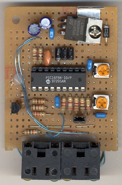
I decided to roll my own TinyTrak, assembled on a protoboard instead of purchasing the circuit board or kit. This decision was based solely on the fact that I wanted it now. Comparing the price of the kit with the component cost and time required to wire the protoboard, it didn’t make much sense to do it the hard way (by wiring a protoboard). However, living in a remote area has the disadvantage that there is a significant wait for everything that comes in the mail. I guess I was impatient. I do have to say in my defense, that I had every required component on hand, even a small enclosure that fit the project perfect.
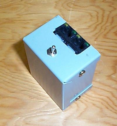
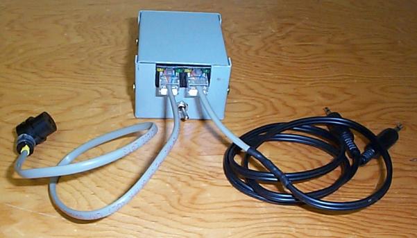
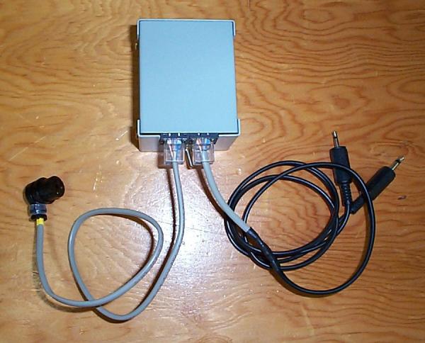
This device was a fairly simple project. Instead of the DB9 serial port on the original PCB I decided to use RJ-45 jacks. The jacks were harvested from some old retired SMC ISA network cards. They were the kind with two (one yellow and one green) LEDs.
The LED’s were perfectly located to indicate the staus of the TrakPak. The layout of the RJ-45 jacks did not match the protoboard hole pattern by any means, but I was able to gently coax the LED leads into the protoboard holes. A few dabs of hotmelt glue held the connectors temporarily attached to the board. The connectors would be firmly attached to the board later, using generous amounts of glue.
The layout of the parts on the board was done from scratch to fit the board dimensions and connectors used. Some minor circuit additions were made on the fly. The actual TinyTrak circuit was powered by a 78L05 voltage regulator as suggested in the construction instructions. The 7806 voltage regulator was added to supply power to the attached GPS if the circuit was powered by an external power source.
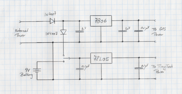
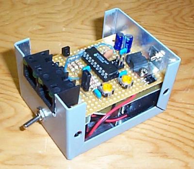
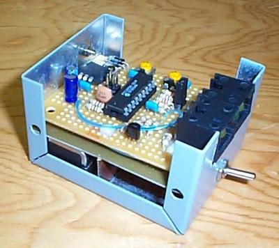
As it turned out, there was sufficient room in the enclosure to house a 9V block battery. The power supply was designed in a way that the internal battery would only power the TinyTrak, not the attached GPS. This allowed for truly portable operation, yet supported powering the TinyTrak and attached GPS via an external power source during mobile operation.
The pinout of the RJ-45 connector was chosen with the thought that one might inadvertendly plug the radio port into the GPS port. Since the radio port would supply power to the circuit this mistake could certainly blow the PIC or voltage regulators if the input power and output power leads were reversed. As can be seen in the table below, the wire pair carrying supply power to the circuit on the radio port are not connected on the GPS port.
| Pin | GPS | Radio |
|---|---|---|
| 1 | Data In | Audio In |
| 2 | GND | GND |
| 3 | N/C | Power In |
| 4 | N/C | GND |
| 5 | Power Out | PTT |
| 6 | GND | GND |
| 7 | Data Out | Audio Out |
| 8 | GND | GND |
The TinyTrak required a programmed PIC16F84-10 microcontroller. The zip file contained the hex file that needed to be burned into the PIC. The process went without a glitch using my trusty old ITU programmer and Nigel Goodwin’s WinPicProg software.
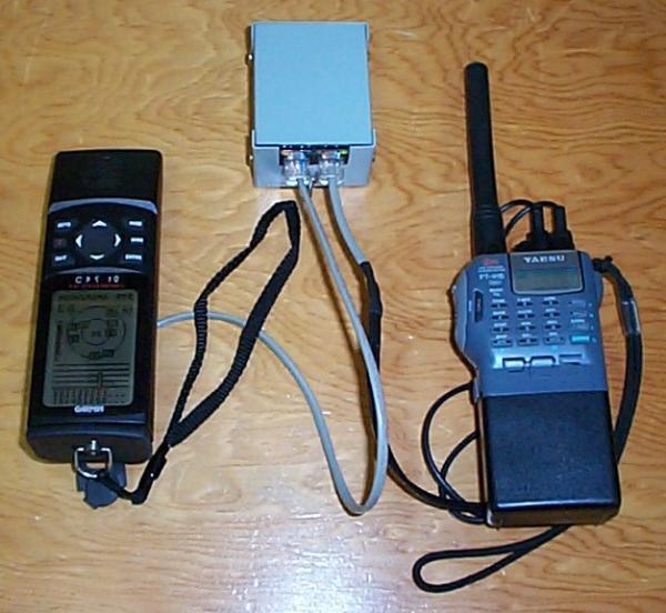
The pictured cables were made for portable operation with my Yaesu FT-416 and Garmin GPS12. The Garmin GPS12 connectors were obtained years ago from PurpleOpenProjects.
All the parts and pieces were assembled for a testrun on my workbench. Everything worked just fine and was finally placed in a small camera bag for a small and compact portable package.
Project resources:
- Byonics, home of TinyTrak.
- PurpleOpenProjects, source for the Garmin power connector.
- B.G.Micro, mail order electronics (supplier of protoboard used).
- Digi-Key, quality electronic components.