BeagleBone GPIO
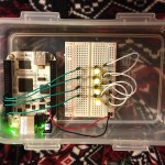
Today I experimented with GPIO on the BeagleBone. After placing the BeagleBone inside a Lock & Lock container with a breadboard I wired up 4 LED. Each LED is driven by a transistor which in turn is driven by a GPIO pin. I used the Debian “Wheezy” install to conduct this experiment with.
The following source of information proved quite helpful in this adventure:
First some considerations about the BeagleBone GPIO. The GPIO pins are muxed to provide many different functions. The GPIO pin naming convention requires a formula to “translate” the reference manual GPIO naming to the Linux system naming for these pins. The explanation for the naming:
GPIO pin naming
GPIO pins on the OMAP processor are known by their “GPIO chip number” and then pin number. In fact the on-board pins are all controlled from the host chip, but the Linux kernel treats all GPIO as pins on external I/O chips (think along the lines of the old 8255 PIO modules). In keeping with the 32 bit nature of this processor the GPIO “chips” each control up to 32 individual pins and there are 4 controller chips. To access a specific pin you need to know the pin’s GPIO number, this is made up of the chip’s base I/O number (i.e. the number assigned to pin 0 of the chip) and the pin number itself. Since there are 32 I/O per chip, and 4 chips starting from zero the base number is the chip number times 32 i.e. GPIO0 base is 0, GPIO1 base is 32, GPIO2 base is 64 and GPIO3 base is 96. So to find the actual GPIO pin number simply take the chip number, multiply by 32 and add the pin.
GPIO3_17 = 3 * 32 + 17 = 113
The LED were wired up to the pins outlined in the table. It also provides the calculation for each of the pins that are needed to control them from a shell script.
| LED | Header | Pin | Mode0 | Mode7 | Formula | GPIO Pin |
|---|---|---|---|---|---|---|
| 1 | P8 | 3 | gpmc_ad6 | GPIO1_6 | 1 * 32 + 6 | 38 |
| 2 | P8 | 12 | gpmc_ad12 | GPIO1_12 | 1 * 32 + 12 | 44 |
| 3 | P8 | 14 | gpmc_ad10 | GPIO0_26 | 0 * 32 + 26 | 26 |
| 4 | P8 | 18 | gpmc_clk | GPIO2_1 | 2 * 32 + 1 | 65 |
The mux settings are accessed via the /sys/kernel/debug path, which turns out to be a file system that requires mounting. In the Debian “Wheezy” installation it is not mounted by default. The command to manually mount dbugfs is
mount -t debugfs none /sys/kernel/debugOr to have debugfs mounted automatically at system boot this is added to /etc/fstab
debugfs /sys/kernel/debug debugfs 0 0
To determine the mux settings for a particular pin, our LED 1 in this example, the following command is run
cat /sys/kernel/debug/omap_mux/gpmc_ad6The result of this is something like
name: gpmc_ad6.gpio1_6 (0x44e10818/0x818 = 0x0037), b NA, t NA
mode: OMAP_PIN_INPUT_PULLUP | OMAP_MUX_MODE7
signals: gpmc_ad6 | mmc1_dat6 | NA | NA | NA | NA | NA | gpio1_6
I ran this for every on of the pins in the table. It already defaulted to Mode 7 which is what is required for GPIO usage.
In order to drive an LED the GPIO pin needs to be configured as output port. It is also helpful to apply a known state the the pin. In this case I elected to make the pin low, which turns the LED off.
    echo 38 > /sys/class/gpio/export
    echo 44 > /sys/class/gpio/export
    echo 26 > /sys/class/gpio/export
    echo 65 > /sys/class/gpio/export

    echo out > /sys/class/gpio/gpio38/direction
    echo out > /sys/class/gpio/gpio44/direction
    echo out > /sys/class/gpio/gpio26/direction
    echo out > /sys/class/gpio/gpio65/direction

    echo 0 > /sys/class/gpio/gpio38/value
    echo 0 > /sys/class/gpio/gpio44/value
    echo 0 > /sys/class/gpio/gpio26/value
    echo 0 > /sys/class/gpio/gpio65/value
To turn a LED on it is just a matter of writing “1” to the “value” of the selected GPIO pin, such as this for LED 3
echo 1 > /sys/class/gpio/gpio26/valueSo far this is pretty boring. Here is a simple bash script that performs a pretty light show.
    #!/bin/bash

    # Define GPIO driving LED
    led="38 44 26 65"

    # Setup GPIO as output and initialize
    for l in $led; do
        echo $l > /sys/class/gpio/export
        echo out > /sys/class/gpio/gpio$l/direction
        echo 0 > /sys/class/gpio/gpio$l/value
    done

    function sequence()
    {
        o=0
        for l in $led; do
            if [ $o -gt 0 ]; then
                echo 0 > /sys/class/gpio/gpio$o/value
            fi
            echo 1 > /sys/class/gpio/gpio$l/value
            o=$l
            sleep 0.5
        done
        echo 0 > /sys/class/gpio/gpio$o/value
    }

    function flash()
    {
        for l in $led; do
            echo 1 > /sys/class/gpio/gpio$l/value
        done
        sleep 0.2
        for l in $led; do
            echo 0 > /sys/class/gpio/gpio$l/value
        done
        sleep 0.5
    }

    # Loop forever and produce a light show
    cnt=1
    while true; do
        if [ $cnt -lt 3 ]; then
            sequence
        fi
        if [ $cnt -gt 2 ]; then
            flash
        for l in $led; do
            echo 0 > /sys/class/gpio/gpio$l/value
        done
        sleep 0.5
    }

    # Loop forever and produce a light show
    cnt=1
    while true; do
        if [ $cnt -lt 3 ]; then
            sequence
        fi
        if [ $cnt -gt 2 ]; then
            flash
        fi

        cnt=$((cnt + 1))
        if [ $cnt -gt 7 ]; then
            cnt=1
        fi
    done
Voila! And this is the result…

