Servo Tester
I needed a device to test R/C servos. Hooking up receiver, battery, servos and then running the transmitter with the antenna extended inside the house was awkward. I thought this could be a nice little project for some microcontroller. After a long abstinence from PIC assembler, I downloaded the latest MPLAB release and programmed away. Here it is, the first cut of my servo tester.
Unfortunately my old parallel port PIC programmer was no longer supported. Since serial ports appear to be a dying breed, a USB programmer was needed. The PICkitII looked like an inexpensive but decent programmer. With support for nearly all current (and many old) PIC devices it was ordered from DigiKey. The PICkitII worked out well, it even supported powering the target from the host PC’s USB port.
A small device to control a standard R/C servo eliminating the need of R/C radio equipment. This device would be useful not only for testing servos but also for installing servos in planes, to adjust center position and throw. Manual control of the servo would be needed as well as a quick way to center a servo. A future enhancement could be an automatic exerciser mode that continuously sweeps the servo at variable speed.
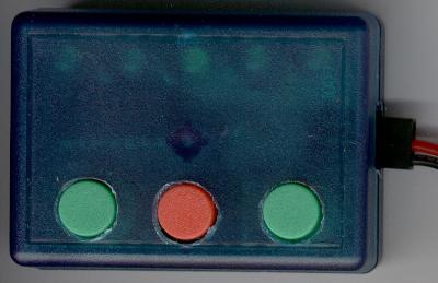
Hardware: Some button were needed to control servo movement, up key, center key and down key. Some LED’s to indicate servo position and connectors to hookup power and one or two servos. In my assortment of electronic parts I found some key switches of unknow origin. I also had a good quantity of LED’s on hand. A translucent green Serpac C-6 enclosure promised a small compact device. A PIC16F676 and a few resistors and capacitors completed the list of parts.
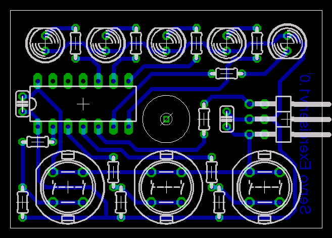
After sketching the schematic on some graph paper, the board layout was designed using the Eagle layout editor. The board was produced using the toner transfer method. Printing the layout onto Epson glossy photo paper with a Dell 1710n printer provided a crisp and flawless image. The paper was ironed onto a freshly scrubbed and cleaned copper clad board. Etching with some well aged Ammonium Persulfate took forever despite heating and agitation. It still resulted in a very good looking board.

This initial version of the software only implemented the manual control of the servo. The exercising function was left for future development. The software runs in a continuous timed loop to generate the output PPM pulses. Timer 1 is used as accurate time base rather then a software delay loop. The hardware was designed to enable the use of the PWM module, even though this first cut of the software does not require or use the PWM functionality.
Version 1.0 History: * First public release
Files: * Source Code * Eagle board * Printable board layout * Schematic Diagram to be added some time